Setting the node address, Setting the i/o configuration – Rockwell Automation 22-COMM-C ControlNet Adapter User Manual
Page 29
Configuring the Adapter
3-3
If the Node Address Switches on the adapter are set to a node address of
“00,” the value of Parameter 02 - [CN Addr Cfg] determines the
ControlNet node address.
1. Set the value of Parameter 02 - [CN Addr Cfg] to a unique node
address.
Figure 3.1 Node Address Screen on PowerFlex 4-Class HIM (22-HIM-*)
Resetting the Adapter on Page 3-6
The I/O configuration determines the number of drives that will be
represented on the network as one node by the adapter. If the Operating
Mode Jumper (J7 in
)
is set to the “1x” (Single mode) default
position, only one drive is represented by the adapter and Parameter 12
- [DSI I/O Cfg] has no effect. If the Operating Mode Jumper is set to the
“5x” (Multi-Drive) position, up to five drives can be represented as one
node by the adapter.
1. Set the value in Parameter 12 - [DSI I/O Cfg].
Figure 3.2 I/O Configuration Screen on Powerflex 4-Class HIM (22-HIM-*)
When the adapter is internally mounted in a PowerFlex 40 or 400
drive, this drive is always Drive 0. Drives 1 through 4 are PowerFlex
Setting the Node Address
Default = 2
CN Addr Cfg
Parameter:
#
002
2
VALUE
LIMITS
SEL
!
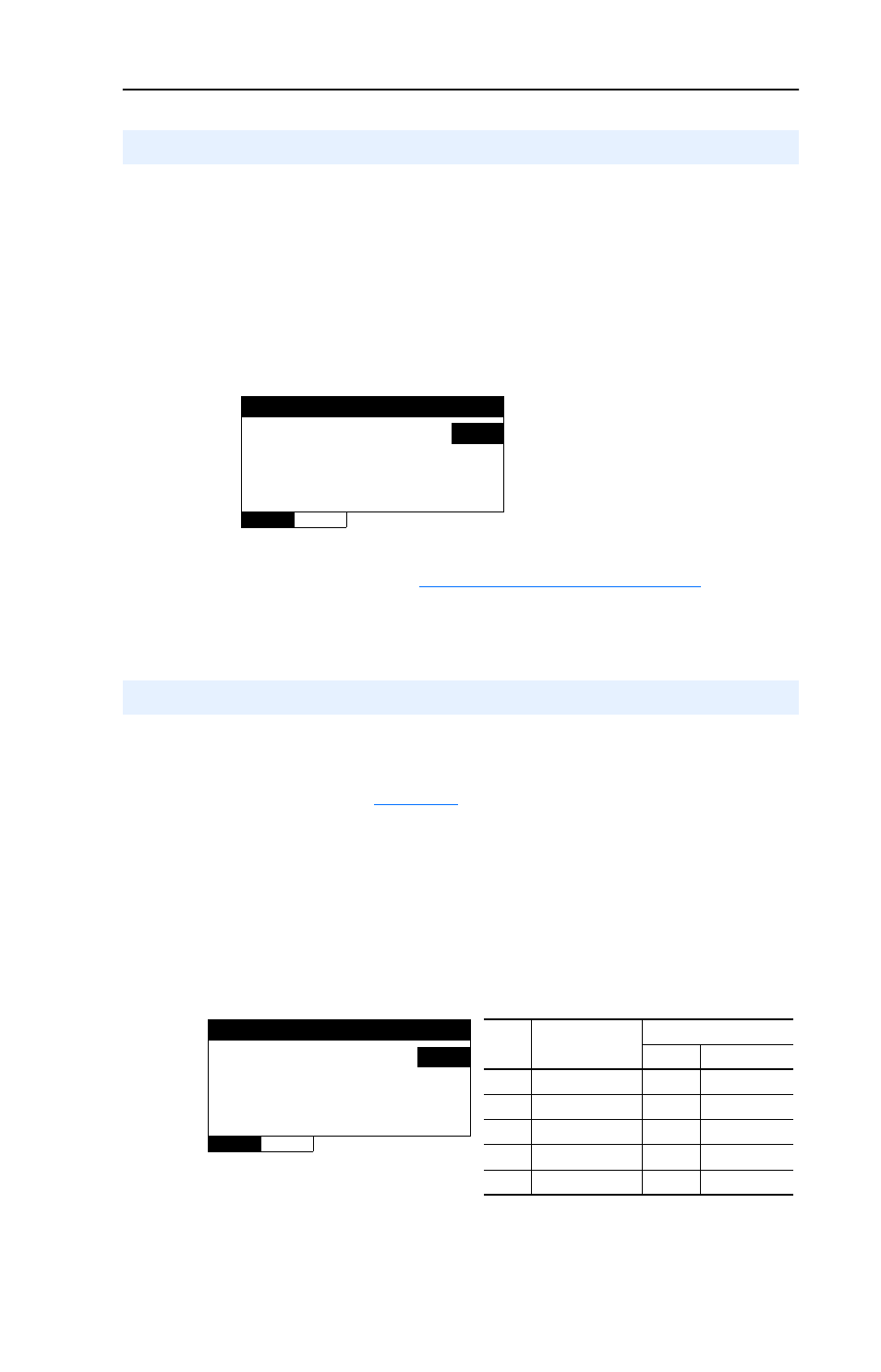
Setting the I/O Configuration
Value Description
Mode Jumper Position
Single Multi-Drive
0
Drive 0 (Default)
✓
✓
1
Drives 0-1
✓
2
Drives 0-2
✓
3
Drives 0-3
✓
4
Drives 0-4
✓
DSI I/O Cfg
Parameter:
#
012
Drive 0
0
VALUE
LIMITS
SEL
!