Enerpac GT-Series User Manual
Page 9
9
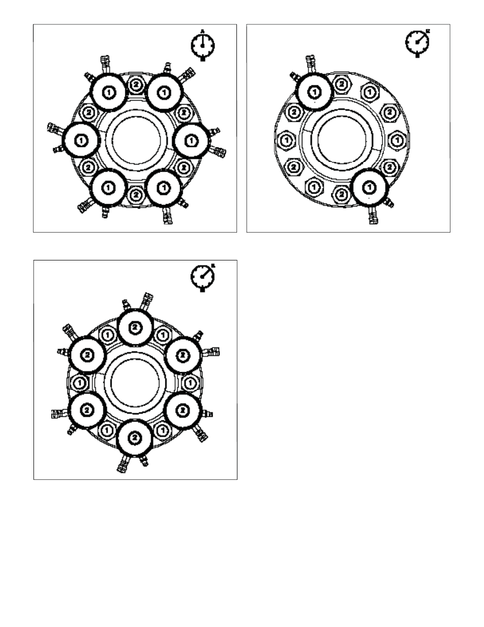
Figure 13, Tensioner Arrangement, Second Pass - Typical
(50% Tensioner Coverage)
Figure 14, Rechecking First Pass Tension
(50% Tensioner Coverage)
Figure 12, Tensioner Arrangement, First Pass - Typical
(50% Tensioner Coverage)
18. When the “second pass” pressure “B” is reached, stop
the pump. Recheck the oil pressure gauge after pump has
stopped. Be sure the pressure remains stable (not increasing
or decreasing). Threads may be visible between the nut and
the joint surface at each tensioner. See Figure 7.
19. While holding the pressure constant, use a tommy bar to turn
down the fi rst socket and nut by hand. Continue tightening
until the nut is fi rmly seated against the joint surface. See
fi gures 8 and 9.
20. Repeat step 19 for the remaining “second pass” tensioners
in the circuit.
21. Release the hydraulic pressure by SLOWLY opening the
pump pressure release (return to tank) valve. Verify that the
oil pressure gauge indicates zero (0) psi/bar. See Figure 10.
22. Check the piston stroke at each tensioner in the circuit. If
necessary, turn down the threaded puller until the piston is
fully retracted into the tensioner body. See Figure 11.
23. Repeat steps 16 through 22 a second time (to pressure “B”).
24. Repeat steps 16 through 22 a third time (to pressure “B”).
25. As an optional check to determine if an excessive
load has been lost in the fi rst 50% of bolts tightened
(bolts numbered “1”):
a. Assemble tensioners on any two “fi rst pass” bolts
(labeled “1”) located diametrically opposite of each other.
See Figure 14.
b. Connect hydraulic hoses.
c. Apply the “second pass” pressure “B”.
d. Using the tommy bar, attempt to tighten the nuts on these
bolts by hand.
• If the nuts cannot be turned, then tensioning is complete.
Relieve hydraulic pressure. Go to Step 26.
• If the nuts can be turned, then re-install the tensioners to
the remainder of the “fi rst pass” bolts (numbered “1”), apply
the “second pass” pressure “B” and turn-down the nuts one
more time as described in steps 16 through 22.
26. Verify that the oil pressure gauge indicates zero (0) psi/bar.
If any pressure is indicated, release the hydraulic pressure
SLOWLY by opening the pump pressure release (return to
tank) valve.
27. Turn down the threaded pullers until the pistons are fully
retracted. Disconnect hydraulic hoses and install a dust
cap (not shown) over each disconnected coupler. Remove
tensioners from the studs.
Apply Pressure “A”
(At all studs marked “1”)
Apply Pressure “B”
(At two diametrically
opposite studs marked “1”)
Apply Pressure “B”
(At all studs marked “2)