Enerpac GT-Series User Manual
Page 10
10
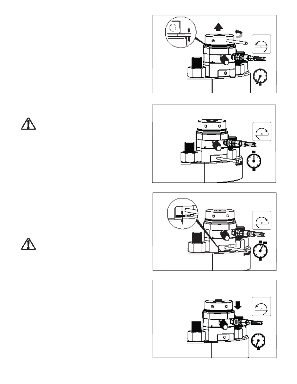
Figure 15, Turning Up the Threaded Puller
Figure 16, Determining the “Break Loose” Pressure
Figure 17, Turning Up the Nut
Figure 18, Pressure Released - Nut De-tensioned
7.3 De-tensioning Instructions - 100% Coverage
(tensioner installed on each stud)
IMPORTANT: Read precautions and instructions at beginning of
Section 7.0 before beginning the following steps. Also refer to
safety information contained in sections 2.1 and 2.2.
Note: For improved illustration clarity, only one hydraulic hose is
shown connected to the tensioner in fi gures 15-18.
1. Assemble the tensioner(s) to the stud(s) to be de-tensioned
and connect the hydraulic hoses. Refer to sections 6.1 and
6.2 for additional tensioner installation and hose connection
instructions.
2.
BEFORE applying any hydraulic pressure, turn up the threaded
puller at each stud as required, so that approximately a 3/16
inch [5 mm] gap appears between the fully retracted piston
and the threaded puller. See Figure 15.
3. Operate the pump to pressurize the tensioners up to
approximately 1000 PSI [70 bar]. Check for oil leaks.
WARNING: In the following de-tensioning steps, be
certain that the hydraulic pressure remains below the
maximum allowable hydraulic pressure of 21,750 psi
[1500 bar], and that the load applied does not exceed the tensile
strength of the stud.
4. If no leaks are found, continue operating the pump. Slowly
raise the pressure until the “break loose” hydraulic pressure
value is reached. This is the pressure at which a nut on one
of the tensioners just begins to loosen and can be turned by
hand with the tommy bar. Record this pressure for reference.
See Figure 16.
5. Increase the hydraulic pressure approximately 5 percent
above the “break loose” pressure recorded in step 4. Then,
stop the pump.
6.
While holding the pressure constant, turn up (loosen) the nut
at the fi rst tensioner, so that there is approximately a 1/8 inch
[3-4 mm] gap between the nut and the joint surface. See
Figure 17.
Note: Dimension of gap in step 6 must not exceed the dimension
of gap in step 2.
7. Repeat step 6 at all remaining studs.
CAUTION: If nuts are diffi cult to turn, hydraulic pressure
may be increased in additional 5 percent increments.
However, NEVER raise hydraulic pressure above 21,750
psi [1500 bar]. Ensure that the load applied does not exceed the
tensile strength of the stud.
8. Release the hydraulic pressure by SLOWLY opening the
pump pressure release (return to tank) valve. Verify that the
oil pressure gauge indicates zero (0) psi/bar. See Figure 18.
The studs are now fully de-tensioned.
9. Turn down the threaded pullers until the pistons are fully
retracted. Disconnect hydraulic hoses and install a dust
cap (not shown) over each disconnected coupler. Remove
tensioners from the studs.
3/16 inch [5mm]
Note: Try to turn up the
nut while slowly raising the
hydraulic pressure. When
the nut just begins to turn,
the “break loose” pressure
(B1) has been reached.
B1= Break Loose Pressure
1/8 inch
[3-4mm]
B2= Break Loose Pressure (B1) + 5%
PRESSURE
RELEASE
OPEN
PRESSURE
RELEASE
CLOSED
PRESSURE
RELEASE
CLOSED
PRESSURE
RELEASE
OPEN