Enerpac GT-Series User Manual
Page 3
3
4.1 Maximum Stroke Indicator
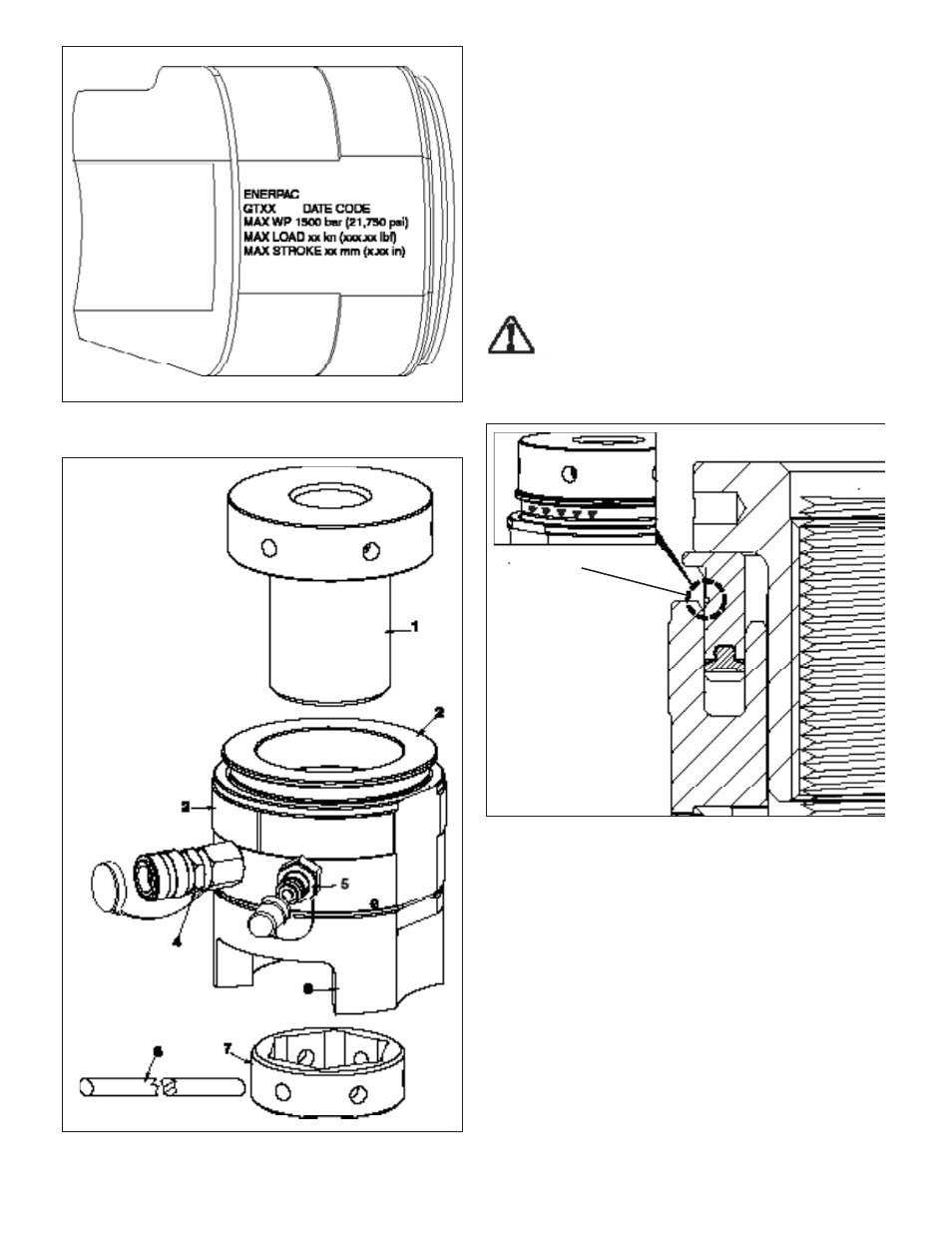
Maximum allowable tensioner stroke is visually indicated by a
yellow painted groove located on the piston’s circumference.
Continually watch for the maximum stroke indicator during
tensioning procedures. Stop pressurizing the system immediately
if the indicator becomes visible.
If during any tensioning procedure, the maximum stroke indicator
appears before the desired hydraulic pressure is reached: STOP
the pump, tighten nut(s) at the tensioner(s) and release hydraulic
pressure. Then, turn down the threaded puller(s) to return the
piston(s) back into the tensioner(s).
To ensure proper tensioning, always repeat the tensioning stage
(start over) if the maximum stroke indicator appears before the
desired hydraulic pressure is reached.
WARNING: Continuing to pressurize the system after
the maximum stroke indicator becomes visible may
result in high pressure hydraulic oil leakage. Serious
personal injury could result if a stream of pressurized hydraulic
oil penetrates the skin. Damage to tensioner components and
joint may also occur if maximum stroke is exceeded.
Maximum
Stroke
Indicator
(Yellow Groove)
Figure 3, Maximum Stroke Indicator
5.0 SETTING UP
5.1 Hydraulic Oil
Oil requirements will vary, depending on pump model and type.
Refer to your pump instruction manual for oil specifi cations.
Failure to use genuine Enerpac hydraulic oil may void warranty.
5.2 Hoses and Fittings
All hydraulic hoses and fi ttings used in the circuit must be rated
at or above the maximum working pressure of the tensioner -
1500 bar [21,750 psi].
To ensure safe and reliable operation, use of Enerpac approved
high pressure hoses is strongly recommended. Refer to the
Enerpac Bolting Solutions Catalog for a complete list of available
hoses, fi ttings and related accessories.
Figure 2, Tensioner Major Components
Key:
1 - Threaded Puller
2 - Piston
3 - Body
4 - Coupler, Female
5 - Coupler, Male
6 - Bridge
7 - Socket
8 - Tommy Bar
Figure 1, Tensioner Data
Note: The tensioner
“load cell” includes
items 2, 3, 4 and 5
(assembled).