Enerpac GT-Series User Manual
Page 7
7
7.0 TENSIONING AND DE-TENSIONING
WARNING: Never stand in-line with the bolt axis while
the system is pressurized. If the bolt should fail,
serious personal injury or death could result if loose or
broken parts become projectiles. All personnel must be aware
of this potential hazard at all times.
WARNING: Ensure that the maximum working pressure
and maximum stroke are not exceeded. Refer to the
specifi cations stamped on the tensioner body. Also see
Table 2 at the end of this document.
IMPORTANT: If the maximum stroke indicator appears at any
time during the following procedures, immediately STOP the
pump, tighten nut(s) at the tensioner(s) and release hydraulic
pressure. Then, turn down the threaded puller(s) to return the
piston(s) back into the tensioner(s) before continuing. Refer to
Section 4.1 for additional information.
IMPORTANT: If any leaks occur, immediately stop the pump and
open the pressure release (return-to-tank) valve. Be sure that
the oil pressure gauge indicates zero (0) psi/bar. Make repairs as
required before continuing with tensioning procedures.
Note: For improved illustration clarity, only one hydraulic hose is
shown connected to the tensioner in fi gures 7-11.
7.1 Tensioning Instructions - 100% Coverage
(tensioner installed on each stud)
IMPORTANT: Read precautions and instructions at beginning of
Section 7.0 before beginning the following steps. Also refer to
safety information contained in sections 2.1 and 2.2.
1. Ensure that the joint is correctly aligned.
2. Assemble the tensioner(s) to the stud(s) and connect
hydraulic hoses. Refer to sections 6.1 and 6.2 for additional
tensioner installation and hose connection instructions.
3. Determine the required hydraulic tensioning pressure. This
value must be calculated by a qualifi ed engineer with bolting
experience.
4. Operate the pump and pressurize the tensioners up to
approximately 1000 PSI [70 bar]. Check for oil leaks.
5. If no leaks are found, continue pressurizing the tensioners
to the calculated value determined in step 3. Continually
observe the tensioner stroke and hydraulic pressure at all
times during pressurization.
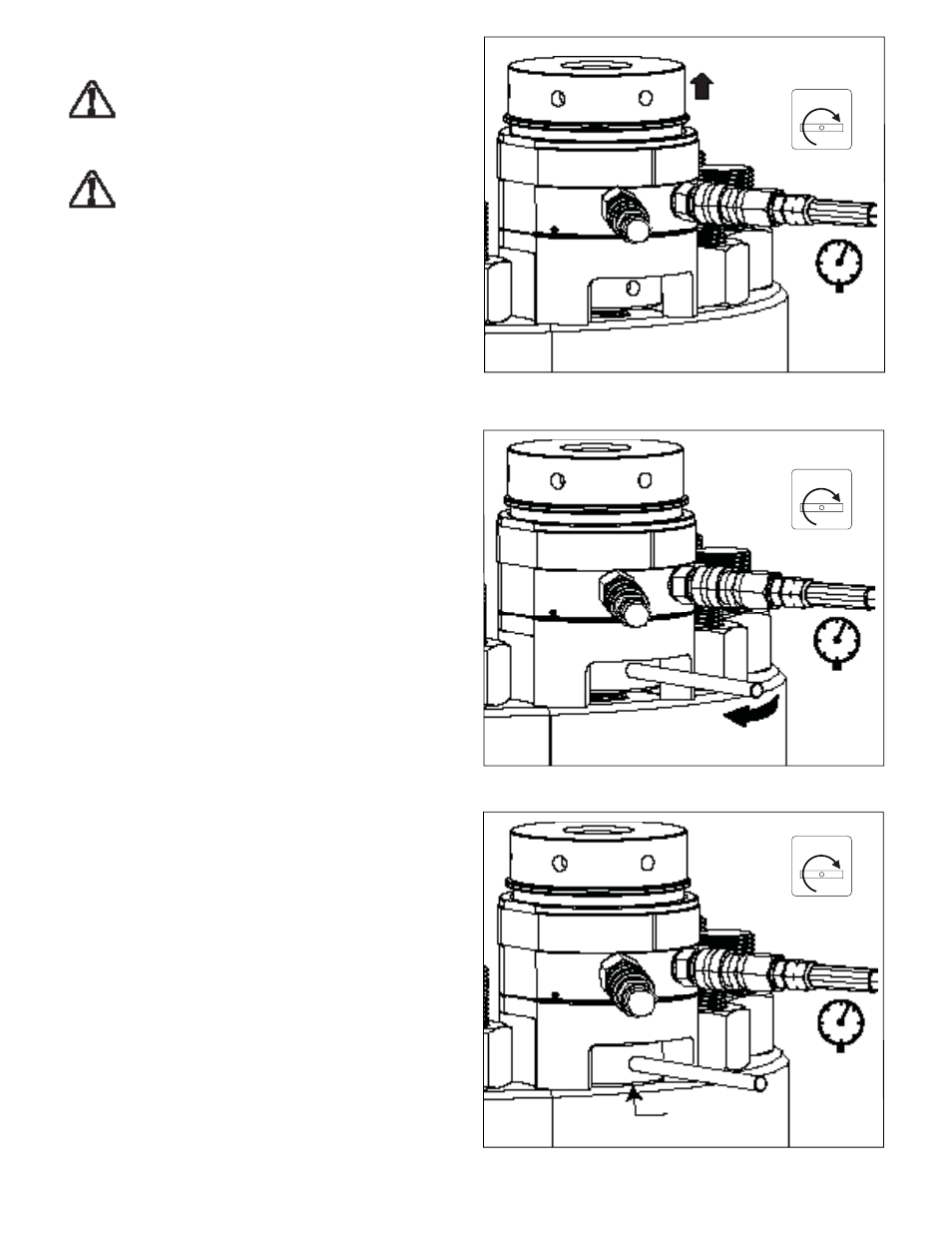
6. When the calculated hydraulic pressure is reached, stop
the pump. Recheck the oil pressure gauge after pump has
stopped. Be sure the pressure is stable (not increasing or
decreasing). Threads may be visible between the nut and the
joint surface at each tensioner. See Figure 7.
7.
While holding the pressure constant, use a tommy bar to turn
down the fi rst socket and nut by hand. Continue tightening
until the nut is fi rmly seated against the joint surface. See
fi gures 8 and 9.
8. Repeat step 7 for all remaining studs in the circuit.
9. Release the hydraulic pressure by SLOWLY opening the
pump pressure release (return to tank) valve. Verify that the
oil pressure gauge indicates zero (0) psi/bar. See Figure 10.
10. Check the piston stroke. If necessary, turn down the threaded
puller until the piston is fully retracted into the tensioner
body. See Figure 11.
11. Repeat steps 4 through 10 a second time.
12. Repeat steps 4 through 10 a third time.
Figure 7, Pressurizing the Tensioner
Figure 8, Turning Down the Socket and Nut
Figure 9, Socket and Nut Firm Against Joint
NO Threads
PRESSURE
RELEASE
CLOSED
PRESSURE
RELEASE
CLOSED
PRESSURE
RELEASE
CLOSED