Enerpac GT-Series User Manual
Page 4
4
6.0 INSTALLATION
6.1 Before You Begin
1. Be sure that ALL calculations (bolt load, hydraulic pressure,
etc.) have been made prior to starting the tensioning
process and that they have been reviewed and approved by
a qualifi ed engineer with bolting experience.
2. Be sure all personnel involved in this procedure are trained
in joint tightening procedures and the tensioning equipment
being used. Ensure that all personnel read and understand
the safety information contained in sections 2.1 and 2.2 of
this document.
3. Be sure that the pump reservoir oil capacity is adequate for
the number of tensioners to be used in the circuit. Refer to
Table 1 for tensioner oil volumes.
Table 1 - Tensioner Oil Volumes
Series
Maximum Oil Volume at Maximum Stroke
(each tensioner)
fl uid ounces (US)
cubic centimeters
GT1
0.65
19,4
GT2
1.16
34,5
GT3
2.25
66,7
GT4
3.95
117,0
GT5
5.84
173,9
GT6
7.63
225,9
Note: To determine total oil volume required, multiply the oil volume
for your tensioner series by the number of tensioners to be used in
the circuit. Oil volumes shown are approximate. Additional oil will be
contained inside hoses and fi ttings.
4. Be sure all personnel are aware of the maximum working
pressure and maximum stroke applicable to the tensioner(s)
being used. This information is stamped on the tensioner
body. See Section 3.0 for additional information.
5.
Inspect the studs to verify that they contain no obvious damage
or defects, and that they appear capable of withstanding the
force that will be applied by the tensioners.
6.
Be sure that all nuts and threaded pullers are free running on
the studs over the entire stud length protruding through the
joint.
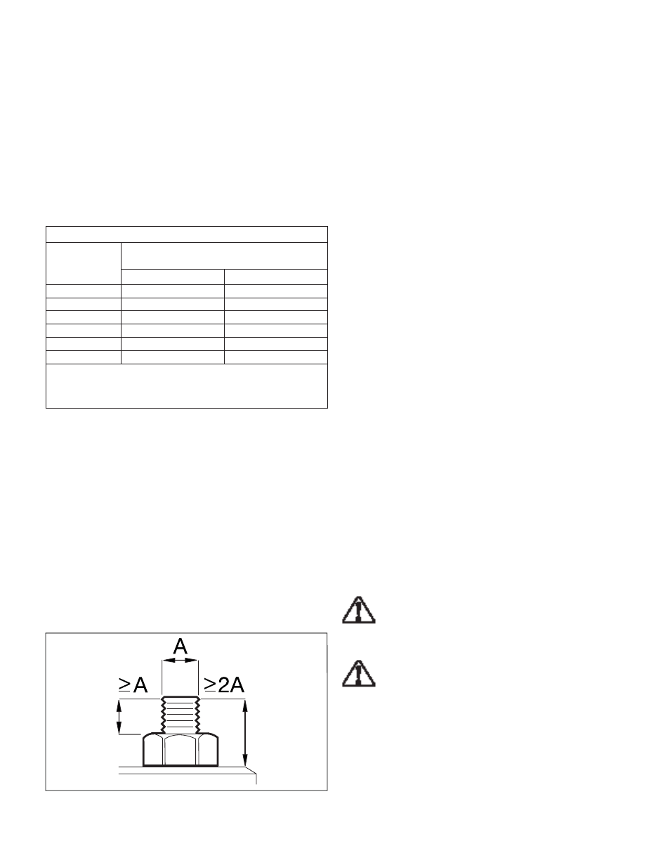
7. Check that each stud is correctly installed and that there
is suffi cient stud extension to engage the tensioner. The
exposed portion of the stud (above the nut) should be at
least the same dimension as the stud diameter. The total
protruding length of the stud (from joint surface to end of
stud) must be at least twice the length of the exposed portion
of the stud. See Figure 4.
Figure 4, Stud Extension Requirements
6.2 Tensioner Installation and Hook-up
1. Refer to Section 6.1, Before You Begin. All personnel to be
involved in tensioning procedures must read, understand
and follow the instructions contained in Section 6.1.
2.
Determine the tensioner arrangement around the joint
surface. Refer to Section 6.3 for examples and additional
information.
3.
Before installing the fi rst tensioner, be sure that the threaded
portions of the stud and threaded puller are clean and free of
damage.
4. Position the socket over the nut. Ensure that the socket fi ts
over the nut without force. See Figure 5, View A.
5. Place the tensioner over the stud. See Figure 5, View B.
a. Ensure that the tommy bar slot in the bridge faces
outward.
b. Ensure that the hydraulic couplers are positioned outward,
to allow easier connection of hydraulic hoses.
6. Locate the end of the stud with the threaded puller. Using
a tommy bar, screw down the threaded puller on the stud
until the puller shoulder seats fi rmly against the piston. See
Figure 5, View C.
7. Assemble any additional tensioners in the system in the
same manner, following steps 3 through 6 of this section.
8. Check that the pump pressure release valve is OPEN. See
Figure 5, View D.
9. Connect hydraulic hoses to the tensioners. See Figure 5,
views E and F. Also refer to Section 6.3 for typical hose
connection arrangements.
10. At each stud, verify that the piston is fully retracted into the
tensioner body. If necessary, turn down the threaded puller
(as required) to fully retract the piston.
11. Before pressurizing the system, be sure that all hydraulic
hoses are connected. Each male coupler must be connected
to a corresponding female coupler. Verify that each coupler is
fully engaged and securely locked into position by physically
pulling on the connection.
IMPORTANT: ONLY the unused female coupler on the LAST
tensioner at the end of the circuit can remain disconnected.
A female coupler can remain disconnected (open ended)
while under pressure. However, as a precaution, it is strongly
recommended that a blanking plug be installed in the coupler
before beginning pressurization.
WARNING: Never pressurize the back side of a
disconnected (open ended) male coupler. Disconnected
male couplers may leak when pressurized from the
back side. Serious personal injury could result if leakage occurs,
and a high pressure oil stream penetrates the skin.
WARNING: If only a single tensioner is being used,
always pressurize the tensioner using ONLY the MALE
tensioner coupler. To prevent possible high pressure oil
leakage, NEVER use the female tensioner coupler to pressurize a
single tensioner.