Enerpac GT-Series User Manual
Page 8
8
13. As an optional check, apply hydraulic pressure a fourth time
and attempt to tighten the nuts again.
• If the nuts cannot be turned, then tensioning is complete.
Relieve hydraulic pressure. Go to Step 14.
• If the nuts can still be turned, repeat steps 4 through 10
until no additional movement can be obtained. However,
caution must be observed as excessive movement may
indicate that a joint problem exists.
14. Verify that the oil pressure gauge indicates zero (0) psi/bar. If
any pressure is indicated, release the hydraulic pressure by
SLOWLY opening the pump pressure release (return to tank)
valve.
15. Turn down the threaded pullers until the pistons are fully
retracted. Disconnect hydraulic hoses and install a dust
cap (not shown) over each disconnected coupler. Remove
tensioners from the studs.
7.2 Tensioning Instructions - 50% Coverage
(tensioner installed on every other stud)
IMPORTANT: Read precautions and instructions at beginning of
Section 7.0 before beginning the following steps. Also refer to
safety information contained in sections 2.1 and 2.2.
1. Ensure that the joint is correctly aligned.
2. Alternately number each bolt “1” and “2” for future
reference.
3. Assemble the tensioner(s) to the studs marked “1” and
connect the hydraulic hoses. See Figure 12 for typical
tensioner arrangement. Also refer to sections 6.1 and 6.2 for
additional tensioner installation and hook-up instructions.
4. Determine
the
“fi rst pass” pressure “A” value. This value
must be calculated by a qualifi ed engineer with bolting
experience.
Note: The pressure “A” value used to tension the bolts marked
“1” is typically higher than the pressure “B” value used later
to tighten the bolts marked “2”. This is to allow for additional
load losses which may occur when performing less than 100%
coverage tensioning.
5. Operate the pump and pressurize the tensioners up to
approximately 1000 PSI [70 bar]. Check for oil leaks.
6. If no leaks are found, restart the pump and pressurize the
tensioners to the “fi rst pass” pressure “A” value determined
in step 4. Continually observe the tensioner stroke and
hydraulic pressure at all times during pressurization.
7. When
the
“fi rst pass” pressure “A” is reached, stop the
pump. Recheck the oil pressure gauge after pump has
stopped. Be sure the pressure remains stable (not increasing
or decreasing). Threads may be visible between the nut and
the joint surface at each tensioner. See Figure 7.
8.
While holding the pressure constant, use a tommy bar to turn
down the fi rst socket and nut by hand. Continue tightening
until the nut is fi rmly seated against the joint surface. See
fi gures 8 and 9.
9.
Repeat step 8 for the remaining “fi rst pass” tensioners in the
circuit.
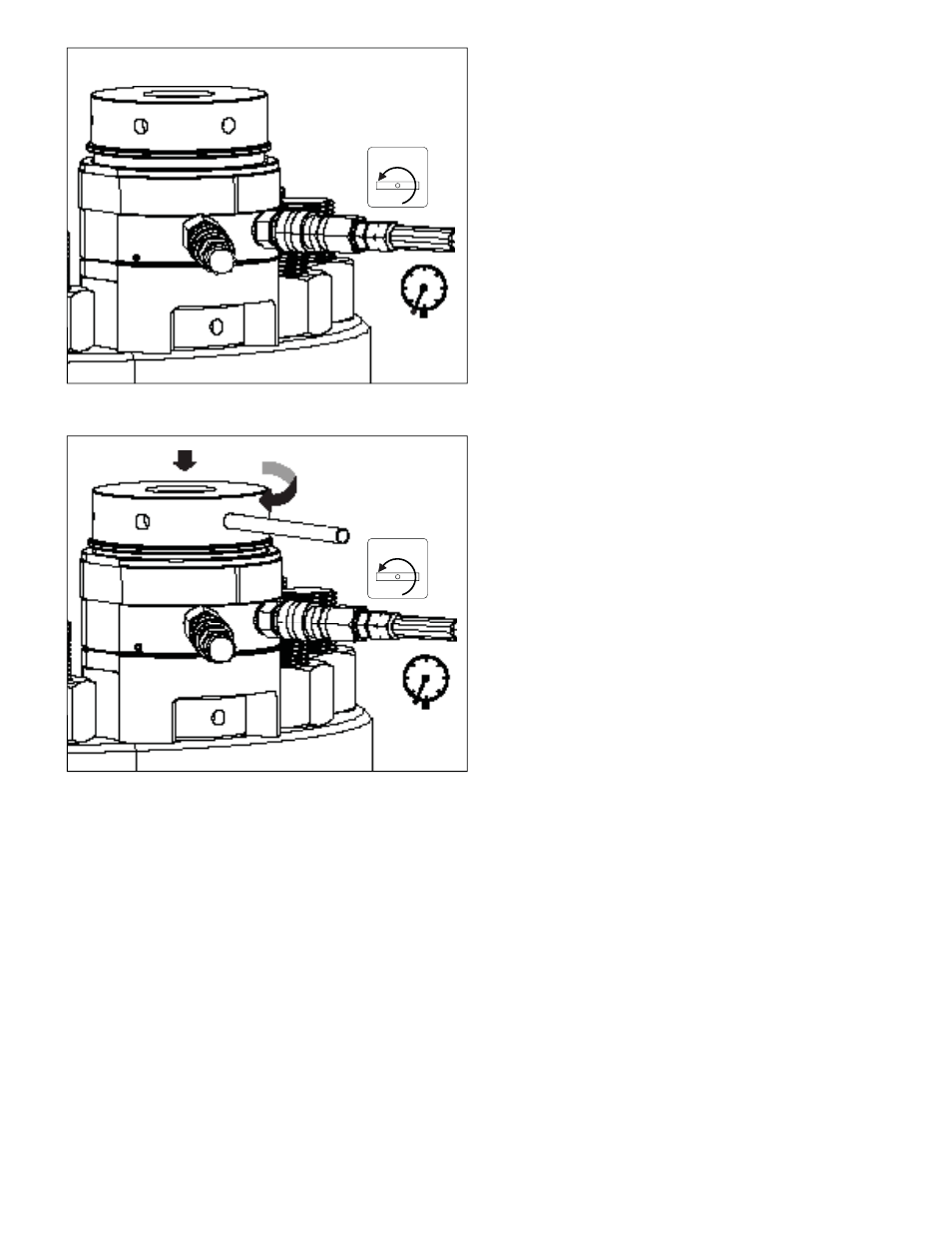
10. Release the hydraulic pressure by SLOWLY opening the
pump pressure release (return to tank) valve. Verify that the
oil pressure gauge indicates zero (0) psi/bar. See Figure 10.
11. Check the piston stroke at each tensioner in the circuit. If
necessary, turn down the threaded puller until the piston is
fully retracted into the tensioner body. See Figure 11.
12. Repeat steps 5 through 11 a second time (to pressure “A”).
13. Repeat steps 5 through 11 a third time (to pressure “A”).
14. Move the tensioners to the remaining 50% of the bolts (i.e.
all bolts numbered “2”). See Figure 13.
15. Determine the “second pass” pressure “B” value. This value
must be calculated by a qualifi ed engineer with bolting
experience.
Note: The pressure “B” value is typically lower than the pressure
“A” value (see note after step 4 for additional information).
16. Operate the pump and pressurize the tensioners up to
approximately 1000 PSI [70 bar]. Check for oil leaks.
17. If no leaks are found, continue pressurizing the tensioners to
the calculated “second pass” pressure “B” value determined
in step 15. Continually observe the tensioner stroke and
hydraulic pressure at all times during pressurization.
Figure 11, Turning Down the Threaded Puller (as required)
Figure 10, Pressure Released After Turning Down Nut
PRESSURE
RELEASE
OPEN
PRESSURE
RELEASE
OPEN