Installation – CHAMPION EEUCCW8 User Manual
Page 29
21
Installation
Installation
Electrical Connections
WARNING:
Electrocution or serious injury may result when working on an
energized circuit.
Disconnect power at the main breaker or service disconnect
switch before working on the circuit.
Lock-out and tag the breaker to indicate that work is being
performed on the circuit.
1. The specific electrical requirements for the
installation of the dishwasher are listed on
the Plumbing and Electrical Diagram
(P& E) that was provided prior to the installation.
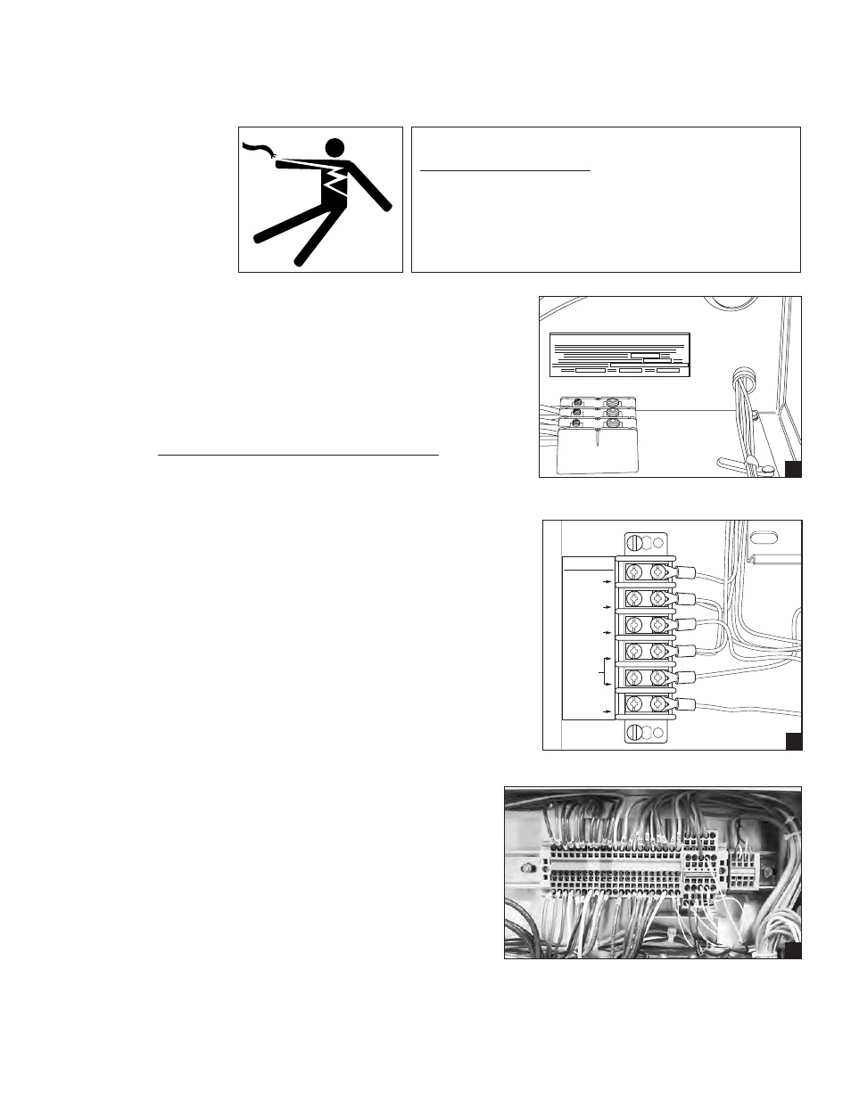
2. The main power supply connection for the
dishwasher (excluding electric booster power) is
made at the main terminal block as shown in (A).
The Machine Electrical Connection Data Plate is
mounted adjacent to the main terminal block and
contains electrical specifications for the
connection.
3. A separate terminal block (B) is located inside
the top-mounted control cabinet which provides
signal voltages for chemical dispensing
equipment or vent fan control if required.
4. The main power connection for the electric
booster (Not Shown) is a separate connection
and is located inside the booster control box.
The box is typically installed on the base of
unload section. The box can also be located
on the top of the dishwasher if specified.
5. Electrical connections between dishwasher
sections are made in wireway boxes (C) that
are mounted on the base of each section.
6. Remove the covers of the wireway boxes and
indentify connecting wires and terminal blocks.
7. Unroll any flexible conduits that were
disconnected from the wireway prior to shipment
and re-route them into the wireway boxes.
8. Refer to the dishwasher electrical schematic and
re-connect the wires between the sections using
the hardware supplied.
9. Re-install the wireway box covers.
MACHINE ELECTRICAL CONNECTION
A
SIGNAL ONLY
VENT FAN
COMMON
COMMON
120V
DETERGENT
120V
RINSE AID
120V
B
C