Figure 12 – Brocade Communications Systems Layer 3 Routing Configuration ICX 6650 User Manual
Page 111
Brocade ICX 6650 Layer 3 Routing Configuration Guide
93
53-1002603-01
Configuring IP parameters – Layer 2 Switches
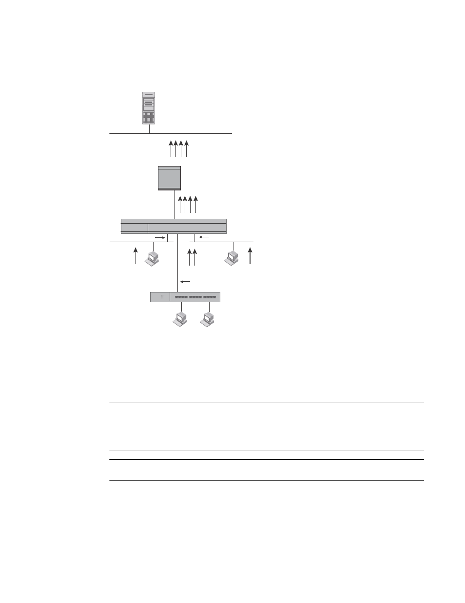
FIGURE 12
DHCP requests in a network with DHCP Assist operating on a FastIron Switch
When the stamped DHCP discovery packet is then received at the router, it is forwarded to the
DHCP server. The DHCP server then extracts the gateway address from each request and assigns
an available IP address within the corresponding IP subnet (
). The IP address is then
forwarded back to the workstation that originated the request.
NOTE
When DHCP Assist is enabled on any port, Layer 2 broadcast packets are forwarded by the CPU.
Unknown unicast and multicast packets are still forwarded in hardware, although selective packets
such as IGMP, are sent to the CPU for analysis. When DHCP Assist is not enabled, Layer 2 broadcast
packets are forwarded in hardware.
NOTE
The DHCP relay function of the connecting router must be turned on.
DHCP
Server
Hub
10.95.7.6
Router
Host 1
Host 2
Host 3
Host 4
192.168.5.x
Subnet 1
10.95.6.x
Subnet 2
10.95.1.x
Subnet 3
10.95.5.x
Subnet 4
Interface 2
Interface 14
Interface 8
Step 1:
DHCP IP address requests
for Hosts 1, 2, 3 and 4 in
Subnets 1, 2, 3 and 4.
Gateway addresses:
192.168.5.1
10.95.6.1
10.95.1.1
10.95.5.1
Step 2:
FastIron stamps each DHCP request
with the gateway address of the
corresponding subnet of the
receiving port.
Step 3:
Router forwards the DHCP request to the
server without touching the gateway
address inserted in the packet by the switch.
Layer 2 Switch