Requirements to be met by the power supply, Example of a power supply connection 1 – Festo Контроллеры двигателя SFC-LAC User Manual
Page 50
3. Installation
3−8
Festo GDCP−SFC−LACI−IO−EN en 0812NH
Requirements to be met by the power supply
Voltage
Use
Currents
48 VDC
+5/−10Ă%
Load supply (pins A1, A2)
Nominal current (peak current): 10 A (20 A)
Internal fuse: 16 A slow−blow (external as an option)
24 VDC ±10Ă%
Logic supply (pins 1, 2)
Nominal current (peak current): 0.4 A (0.8 A)
Internal fuse: 4 A slow−blow (external as an option)
Local outputs OUT1/2
Supply via logic supply (pins 1, 2).
Max. 1 A permissible per output.
Hardware enable (pins 3, 5)
Minimum current on contact for the load voltage.
Total
Dependent on the system architecture, up to 3.8 A.
24 VDC ±10Ă%
Supply of the outputs of the conĆ
troller interface
Connection and pin assignment:
see section 3.6.
Idle current: 0.05 A
Peak current (max. 0.5 A per output): 2.1 A
Tab. 3/4: Requirements to be met by the power supply
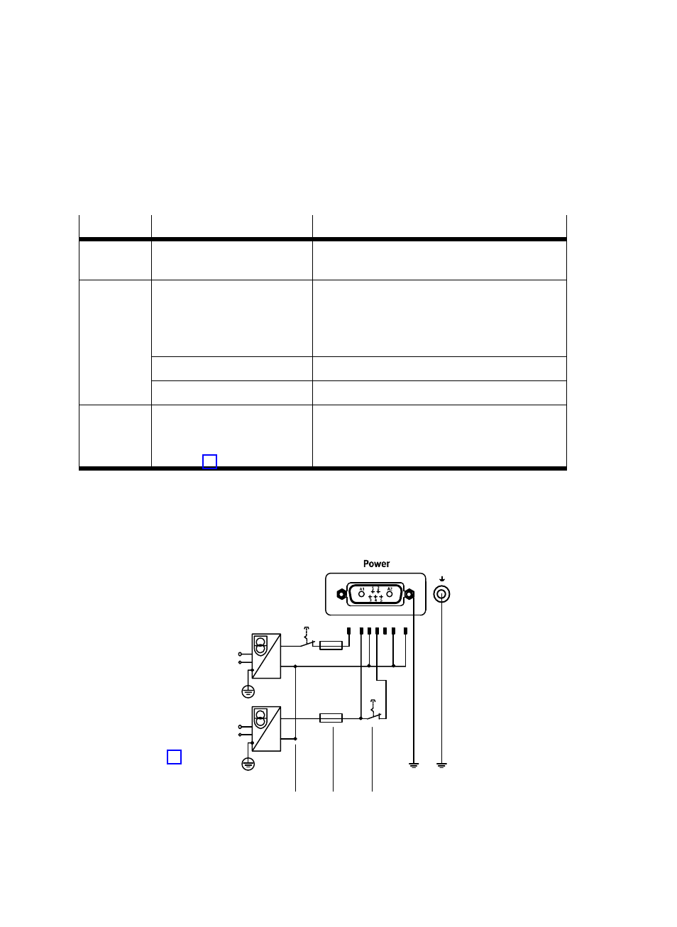
Example of a power supply connection
1
Connect the
earth terminals
of the two power
supply units.
2
External fuses
(as an option)
3
Switch for
hardware enable
4
Earth terminals
(only use one,
see Ăsection 3.3)
1 2 3 4
A1
5
A2
1
2
3
4
Fig. 3/2:
Power supply connection example