Seed Hawk 30 SERIES: 600C & 800C 2013 User Manual
Page 28
SEED HAWK® 30 SERIES OPERATOR’S MANUAL
28
NOTE: Seed and fertilizer depth are always measured down from the packed surface of the
furrow. The seed and fertilizer knives are mounted at a fixed distance apart on the opener arm
assembly. The knives are also offset laterally to place seed and fertilizer in adjacent, yet
separate, furrows. The packer/gauge wheel packs the soil around the complete disturbed areas
of the furrows to ensure optimum seed/soil contact and fertilizer placement as well as
maintaining available soil moisture. Hydraulic pressure to the main arm assemblies is
controlled and adjusted from the tractor. IT IS THE RESPONSIBILITY OF THE OPERATOR OF
THE TOOLBAR TO CHECK THE SEED DEPTH ACROSS THE TOOLBAR AT EVERY FIELD.
3.6.2 SEED DEPTH
Placing the seed at the proper depth and keeping the depth setting consistent are critical to
achieving optimum germination. The packer wheels are factory set to place seed at a depth of
0.75in (19 mm) below the packed surface of the soil. Fertilizer is placed approximately 0.75in
(19 mm) below and 1.50 in (38 mm) to the side of the seed.
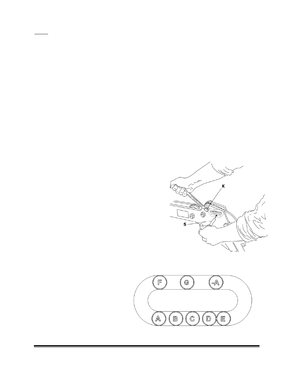
TO ADJUST SEED DEPTH:
1. Remove retaining pin from depth setting Quick
Pin (S), SEE FIGURE 3.2.
2. Remove depth setting Quick Pin from opener
shank.
3. Select desired depth setting using the settings,
on the opener, FIGURE 3.3, indicated on the
opener.
4. Use a ¾” wrench on hex, (K) FIGURE 3.2, rotate
gear to align desired depth setting.
5. Insert depth setting pin (S) and replace retaining
pin.
6. Depth measurement settings. These settings
are approximate and it is still the responsibility
of the operator to check where the seed and
fertilizer is being place. SEE FIGURE 3.3.
A = 3/8”
B = 1/2”
C = 5/8”
D = 3/4”
E = 1”
F = 1‐1/4”
G = 1‐1/2”
‐A= less than 3/8”
FIGURE 3.3
FIGURE 3.2