Digital adapter options, Ough 67, F2 remove – PASCO Xplorer-GLX Users’ Guide User Manual
Page 73
X p l o r e r G L X U s e r s ’ G u i d e
67
If both carts are traveling in the same direction before the collision, one photo-
gate will measure the initial velocity of both carts. Similarly, if both carts are
traveling in the same direction after the collision, one photogate will measure
both final velocities.
If one of the carts is stationary before the collision, its initial position will be
between the photogates, and its initial velocity will not be measured. If one of the
carts is stationary after the collision, its final velocity will not be measured.
Digital Input
Select the Digital Input timer
22
to record the state changes of a
photogate or other switch-type sensor.
This timer measures the sensor’s Logic State, which has only two possible val-
ues: 0 and 1. A Logic State value of 0 corresponds to a sensor output voltage of
0 V, and a value of 1 corresponds to an output voltage of 5 V.
In the case of a photogate, if the most recently recorded Logic State value is 0,
then the photogate is blocked; if the most recent value is 1, then the photogate is
unblocked. A data point is recorded each time the sensor changes states; thus
when the photogate switches from being unblocked to blocked, the timer records
0, and when the photogate switches from blocked to unblocked, the timer
records 1.
Typically, the interesting data recorded by the Digital Input timer is not the
0-or-1 Logic State value, but rather the time-stamps recorded with those values.
To see the time data, view Time in one column of the Table display and Logic
State in another column.
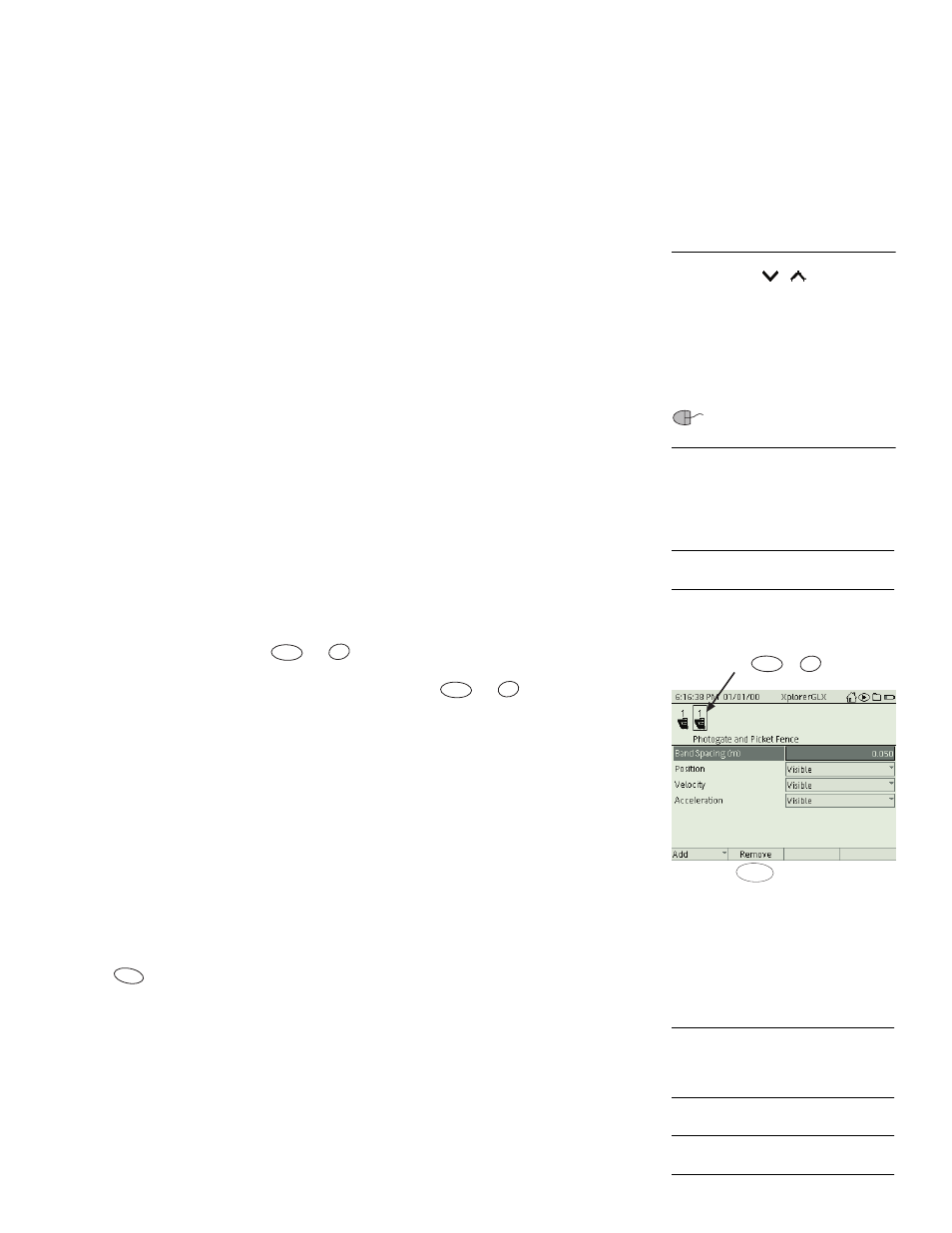
F2 Remove
To remove a timer, press
or
. If you have more than one timer set up,
first use the left and right arrow keys (or mouse) to select the timer that you want
to remove in the upper part of the screen, then press
or
.
If there are data collected by that timer, they will be permanently deleted. (The
GLX will ask you for confirmation before it deletes the timer.)
Digital Adapter Options
In addition to switch-type sensors, the Digital Adapter (PS-2159) allows the
GLX to be used with a ScienceWorkshop Motion Sensor, a ScienceWorkshop
Rotary Motion Sensor, or a Digital Relay.
To set up the GLX for one of these devices, connect the Digital Adapter to the
GLX and connect the sensor or relay to the adapter (in either order). The Add
menu will open automatically with Motion Sensor, Rotary Motion Sensor, and
Relay Control among the options. (These options do not appear if you press
to open the menu.)
ScienceWorkshop Motion Sensor or Rotary Motion Sensor
To use one
of these sensors
with a Digital Adapter, connect the yellow and black plugs of
the sensor to ports 1 and 2 (respectively) of the adapter and connect the adapter to
the GLX. The Add menu will open automatically; select Motion Sensor or
Rotary Motion Sensor. To set the sample rate and other sensor properties, go the
Sensors screen (see page 55).
Relay Control
To set up the GLX for control of a Digital Relay
through a
Digital Adapter, connect the relay to the adapter and connect the adapter to the
22
If the Add menu is too long to fit on the
screen, arrows (
,
) appear on the
menu to indicate that some of the menu
options are not visible.
Press the up or down arrow key multiple
times to move the highlight beyond the
visible portion of the menu. The menu will
scroll to bring other options into view.
If you are using a mouse, you can
click the arrows to scroll the menu.
23
See page 28 for instructions on choos-
ing data to display in the Table.
F2
Select the timer to be deleted
and press or
Õ
F2
F2
Õ
F2
Õ
F1
24
The
ScienceWorkshop Motion Sensor
is PASCO part CI-6742. The
ScienceWorkshop Rotary Motion Sen-
sor is PASCO part CI-6538.
25
The Digital Relay is PASCO part
CI-6462.