Procedure – PASCO Xplorer-GLX Users’ Guide User Manual
Page 138
132 C a p a c i t o r
D i s c h a r g e
4.
When the GLX asks if you would like to save the previous file, press
to save or
not to save.
Procedure
Equipment Set-Up
1.
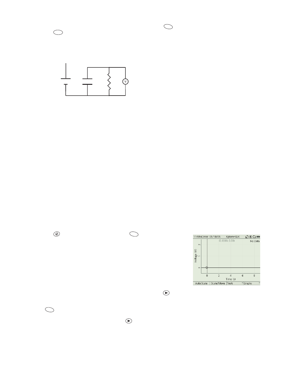
Create the circuit pictured above. Note that the negative terminal of the bat-
tery is connected, but the positive terminal is not. The voltage probe is con-
nected so that it will measure the voltage across the capacitor.
2.
Record your values of capacitance and resistance. (Measure them directly if
you have capacitance and resistance meters, or record their nominal values.)
C = __________________
R = __________________
GLX Set-Up
1.
Connect the voltage probe to the GLX.
a)
Connect the voltage probe to the voltage port on the left side of the
GLX.
b)
If there are other sensors connected, remove them.
2.
Set up the Graph to plot Voltage versus Time.
Press
to return to the Home Screen; press
to open the Graph.
The display will be automatically set up to graph Voltage versus Time.
Data Collection
1.
Charge the capacitor by temporarily connecting the positive terminal of the
battery to the positive terminal of the capacitor. Keep the connection for
about 5 seconds before proceeding to the next step. (Do not leave this con-
nection in place for too long, as it will drain the battery.)
2.
Disconnect the positive terminal of the battery and immediately press
to
start data collection.
3.
Press
to automatically scale the Graph.
4.
After the voltage has dropped below 0.1 V, press
to stop data collection.
F1
F2
C
R
voltage
probe
+
-
+
-
resistor
capacitor
battery
+
-
Graph prepared to plot
V vs. t
F1
F1