Extron Electronics DMS 1600_2000_3200_3600 User Guide User Manual
Page 60
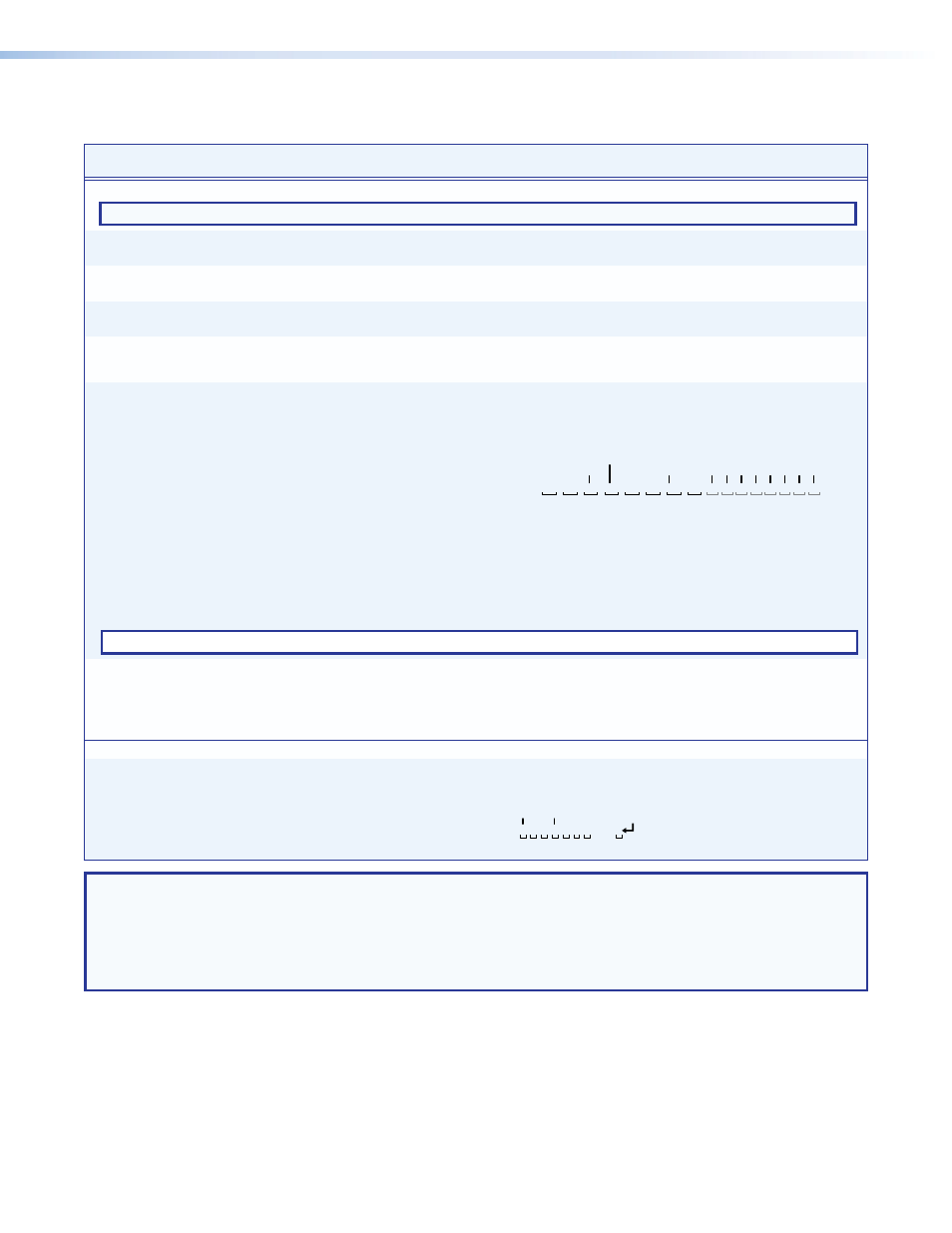
Command and Response Table for SIS Commands (continued)
DMS 1600, DMS 2000, DMS 3200, and DMS 3600 • Programming Guide
54
Command
ASCII Command
(Host to Unit)
Response
(Unit to Host)
Additional Description
View ties, mutes, and presets
NOTE: The
! read tie command, & read tie command, and % read tie command can be used interchangeably.
Read tied input
X@
!
X!
]
Input
X!
is tied to output
X@
.
Example:
1!
05
]
Input 5 is tied to output 1.
Read tied input, RGB output
X@
&
X!]
Input
X!
is tied to output
X@
.
Example:
15&
27]
Input 27 is tied to output 15.
Read tied input, Vid output
X@
%
X!]
Input
X!
is tied to output
X@
.
Example:
7%
02
]
Input 2 is tied to output 7.
View status of all output
mutes
E
VM
}
X#
1
X#
2
X#
3
...
X#
n
]
Each X# response is the mute status of an
output, starting from output 1. n is the
highest-numbered output.
View global preset
configuration
EX^
*
X@
*1VC
}
X!
n
•
X!
n+1
•...
X!
n+15
•Vid
]
Show the configuration of preset X^. Show
the input tied to 16 consecutive outputs,
starting from output X@.
Command description:
Preset # (
X^
)*starting output# (
X@
)*1VC
Response description:
Input # (
X!
n
) tied to output # (
X@
)•
X!
n+1
tied to
X@
•
X!
n+2
tied to
X@
• ... •
X!
n+15
tied to
X@
•Vid
]
Example (8x8 matrix):
E
23*1*1VC}
1
Output:
Response = tied input:
input 2 tied to output 3
2
3
4
5
6
7
8
08•08•02•08•08•01•00•00
no tied input
input 8 tied to output 4
•--•--•--•--•--•--•--•--•
13 14 15 16
09 10 11 12
outputs do not exist
•Vid
]
Each position shown in the response is an output: left = starting output number
(1 in this example), right = starting output +15 (16 in this example). (Outputs
9 through 16 are not present on this matrix switcher.) The number in each
position is the input tied to that output.
In this example, for preset 23, video input 8 is tied to outputs 1, 2, 4, and 5;
input 2 is tied to output 3; and input 1 is tied to output 6. No inputs are tied to
outputs 7 and 8.
NOTE:
EX^
*1*1VC
}
where
X^
= 0 returns the current video configuration of the switcher.
View room preset
configuration
EX&
*
X(
*
X@
*1VC
}
X!
n
•
X!
n+1
•...
X!
n+15
•Vid
]
Show the configuration for room X&, preset
X(. Show the input tied to 16 consecutive
outputs, starting from output X@.
Command description:
Room # (
X&
)*room preset # (
X(
)*starting output# (
X@
)*1VC
Response description:
Input # (
X!
n
) tied to output # (
X@
)•
X!
n+1
tied to
X@
•
X!
n+2
tied to
X@
• ... •
X!
n+15
tied to
X@
•Vid
]
DSVP
List all connections
0LS
X1)
1
X1)
2
X1)
3
...
X1)
n
]
Each X1) response is the connection status
of an input, starting from input 1. n is the
highest-numbered input.
Example (32x32 matrix):
0LS
Input:
Response Status:
no input detected
0 0 0 1 1 1 0 . . . 0
input detected
1 2 3 4 5 6 7
32
NOTE:
X!
= Input number (for tie)
00 – 16 (20, 32, 36) (00 = untied)
X@
= Output number
01 – 16 (20, 32, 36)
X#
= Mute status
0 = not muted
1 = muted
X^
= Global preset number
00 through 32
X&
= Room number (for room presets)
01 through 10 (each can have up to 10 room presets [
X(
s] assigned)
X(
= Room preset number
01 through 10
X1)
= Connection status
0 = no input connected 1 = input connected