Rear panel cabling and features, Dvi input connectors (see page 10 ), Dvi output connectors (see page 10 ) – Extron Electronics DMS 1600_2000_3200_3600 User Guide User Manual
Page 13: Lan (ethernet) connector (see page 11 ), Fiber optic input connectors (see page 11 ), Reset button and led (see page 12 ), Fiber optic output connectors (see page 11 ), Power connectors (see page 13 )
DMS 1600, DMS 2000, DMS 3200, and DMS 3600 • Installation
7
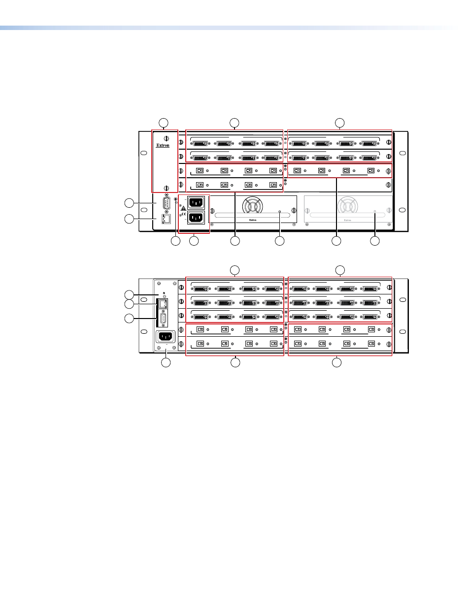
Rear Panel Cabling and Features
Figure 3, below, shows a DMS 1600. Figure 4, below, shows a DMS 2000.
, on the next page, shows a DMS 3600. The four
models have similar features, but different-sized enclosures and a different arrangement of
the features.The DMS 2000 and DMS 3200 do not have swappable power supplies or fan
assemblies. The DMS 3600 has two fan assemblies.
ANAHEIM, CA
RESET
REMO
TE
RS-232/RS-422
LAN
1 - 4
5 - 8
9 - 12
13 - 16
LINK
AC
T
REDUNDANT
100-240V
50-60Hz
1.2A MAX.
PRIMARY
100-240V
50-60Hz
1.2A MAX.
DISCONNECT BO
TH PO
WER
CORDS BEFORE SER
VICING
PRIMARY POWER SUPPLY
REDUNDANT POWER SUPPLY
A
B
TMDS
FIBER
INPUTS
C
D
A
B
DVI-D INPUTS
DVI-D OUTPUTS
C
D
A
B
C
D
DMS 44 DVI
A
B
DVI-D INPUTS
DVI-D OUTPUTS
C
D
A
B
C
D
DMS 44 DVI
A
B
TMDS
FIBER
INPUTS
C
D
A
B
TMDS
FIBER
OUTPUTS
DMS FIBER 44
C
D
1
1
1
2
REDUNDANT
100-240V
50-60Hz
1.2A MAX.
PRIMARY
100-240V
50-60Hz
1.2A MAX.
DISCONNECT BO
TH PO
WER
CORDS BEFORE SER
VICING
9
9
7
5
6
1
10
1
8
1
3
4
Figure 3.
DMS 1600 Matrix Switcher Rear Panel
RESET
LAN
REMOTE
100-240V 50/60Hz
2.0A MAX
1 - 4
5 - 8
9 - 12
13- 16
17 - 20
A
B
DVI-D INPUTS
DVI-D OUTPUTS
C
D
A
B
C
D
DMS 44 DVI
A
B
DVI-D INPUTS
DVI-D OUTPUTS
C
D
A
B
C
D
DMS 44 DVI
A
B
DVI-D INPUTS
DVI-D OUTPUTS
C
D
A
B
C
D
DMS 44 DVI
A
B
TMDS
FIBER
INPUTS
C
D
A
B
TMDS
FIBER
OUTPUTS
DMS FIBER 44
C
D
A
B
TMDS
FIBER
INPUTS
C
D
A
B
TMDS
FIBER
OUTPUTS
DMS FIBER 44
C
D
5
8
7
6
1
1
1
2
1
3
4
Figure 4.
DMS 2000 Matrix Switcher Rear Panel
a
DVI input connectors (see
e
Remote (RS-232/RS-422) port (see
)
b
DVI output connectors (see
f
LAN (Ethernet) connector (see
)
c
Fiber optic input connectors (see
)
g
Reset button and LED (see
d
Fiber optic output connectors (see
)
h
Power connectors (see
)
i
Power indicator LEDs (DMS 1600 and DMS 3600 only) (see
)
j
Cooling fan assemblies (DMS 1600 and DMS 3600 only) (see