Removing the i/o board or blank panel, Installing the i/o board or blank panel, Align with plastic chassis guides – Extron Electronics DMS 1600_2000_3200_3600 User Guide User Manual
Page 108: Knurled knobs, A connectors d connectors
DMS 1600, DMS 2000, DMS 3200, and DMS 3600 • Maintenance and Modifications 102
ATTENTION: Do not touch the electronic components or the backplane or circuit
board connectors without being electrically grounded. Handle circuit boards by their
edges only. ESD can damage circuits, even if you cannot feel, see, or hear it.
NOTE: The boards are hot-swappable. You do not need to power down the switcher to
remove or install a board.
Removing the I/O Board or Blank Panel
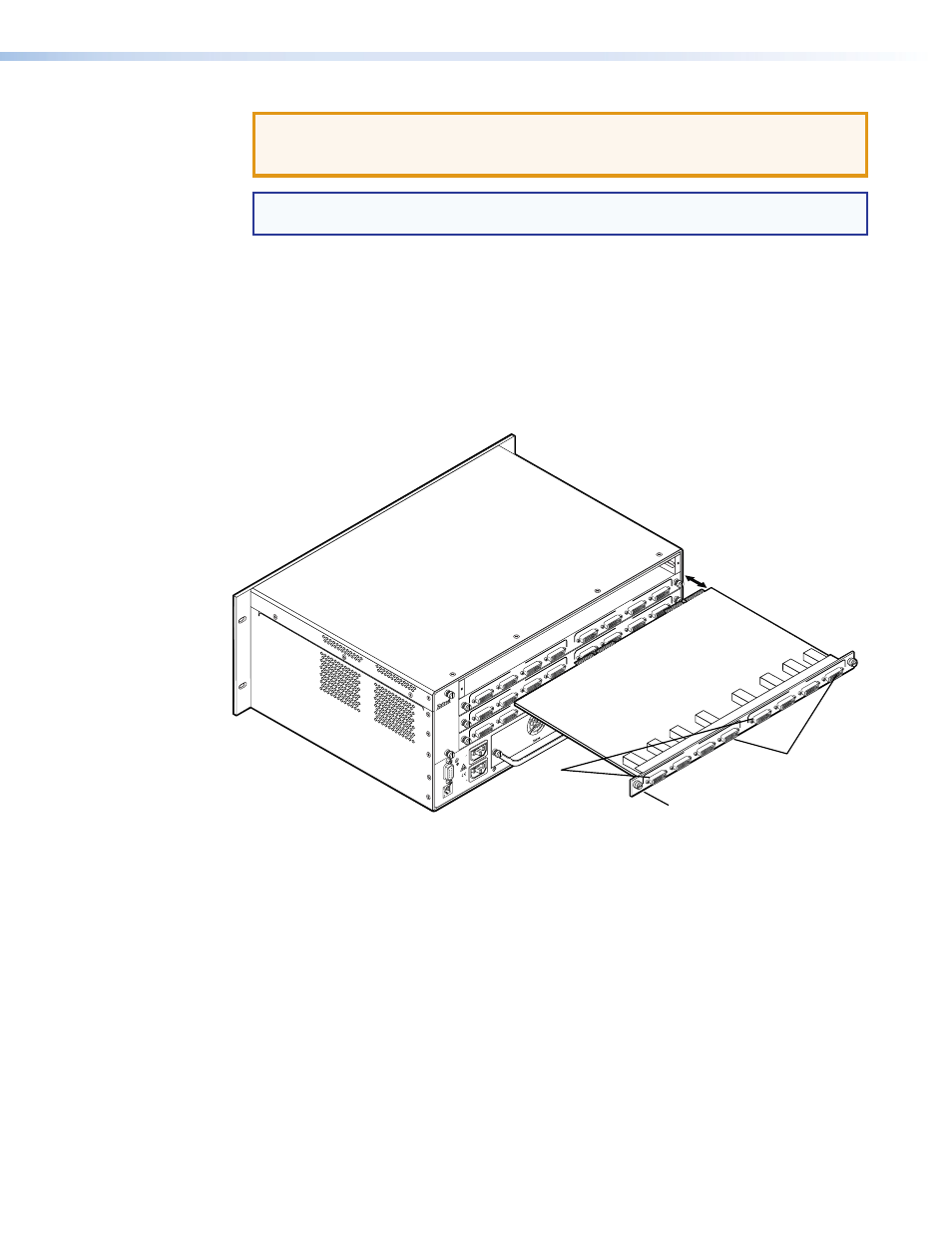
Remove an input/output board, input board, output board, or blank panel as follows:
1.
For a board, disconnect any connected cables.
2.
Rotate the left and right knurled knobs to completely loosen the screws.
3.
Gently pull on the screws to loosen the board or panel from the backplane.
4.
Slide the board or panel out of the chassis (see figure 68).
ANAHEIM, CA
RESET
REMOTE
RS-232/RS-422
LAN
BI-LEVEL
TRI-LEVEL
ACT LINK
PRIMAR
Y POWER SUPPL
Y
REDUNDANT
POWE
R SUP
PLY
1 - 8
9 - 16
17 - 24
25 - 32
Align with plastic chassis guides.
100-
240V
50/
60H
z
1.2A
MA
X.
100-
240V
50/
60H
z
1.2A
MA
X.
RE
DUND
AN
T
PRIM
AR
Y
DIS
CO
NN
ECT
BOTH
POWER
CORDS BE
FORE
SERVICI
NG
A
B
DVI-D INPUTS
DVI-D OUTPUTS
DM
S 44
DVI
C
D
A
B
C
D
A
B
DVI-D INPUTS
DVI-D OUTPUTS
DM
S 44
DVI
C
D
A
B
C
D
A
B
DVI-D INPUTS
DVI-D OUTPUTS
DM
S 44
DVI
C
D
A
B
C
D
Knurled Knobs
A
B
DVI-D INPUTS
DVI-D OUTPUTS
DM
S 44
DVI
C
D
A
B
C
D
A
Connectors
D
Connectors
Figure 68.
I/O Board Replacement
5.
Place the removed board on an antistatic surface or in an antistatic container.
Installing the I/O Board or Blank Panel
Install an input/output board, input board, output board, or blank panel as follows:
1.
For a board, orient the board to be installed so that the A connectors are on the left
and the D connectors are on the right as you face the rear of the switcher.
2.
For a board, align the board with the left and right plastic chassis guides
(see figure 68, above).
3.
Gently slide the board or blank panel into the enclosure.
For a board, slide the board
toward the front panel until it meets resistance.
4.
Gently seat the board or panel in the backplane.
5.
Use a screwdriver to tighten the left and right screws to lock the board or panel in place.