Extron Electronics DMS 1600_2000_3200_3600 User Guide User Manual
Page 16
DMS 1600, DMS 2000, DMS 3200, and DMS 3600 • Installation
10
Below are installation guidelines for the switcher configuration; if you incorrectly order the
I/O boards, the switcher will not recognize some inputs, outputs, or both.
•
You
must install a 4x4 DVI or fiber optic input and output board in the top slot (slot 1).
•
You can install any of the six board types (a 4x4 DVI or fiber optic input and output
board, a 4 DVI or fiber optic input board, or a 4 DVI or fiber optic output board) or a
blank panel in the next slot (slot 2).
•
You can install any of the board types in the slot directly underneath a 4x4 input and
output board.
•
After you install a 4-input board or 4-output board, all active boards underneath it
must
be the same size (4-input or 4-output).
•
Within these size guidelines (4-input must follow 4-input or 4-output must follow
4-output), you can follow a DVI board with a fiber optic board or follow a fiber optic
board with a DVI board.
•
If you install a blank panel, all slots under it
must contain blank panels (you cannot skip
a slot).
I/O connections
WARNING: Risk of serious physical injury — The DMS fiber optic I/O boards output
continuous invisible light, which may be harmful to the eyes; use with caution. For
additional safety, plug the attached dust caps into the optical transceivers when the
fiber cable is unplugged.
NOTES:
•
Fiber optic boards: Ensure that you use multimode fiber cable for your I/O board.
Typically, multimode cable has an orange or aqua jacket.
•
DVI boards: Although the DVI I/O boards use DVI-I connectors, the switchers
handle only DVI-D (digital) video and the boards are labeled “DVI-D.”
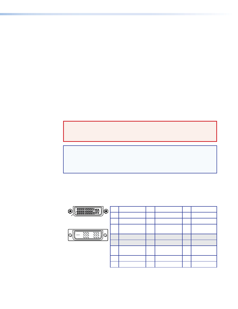
a
DVI-D Inputs ports — Connect DVI cables between these ports and the DVI output
ports of the digital video sources (see figure 8).
b
DVI-D Outputs ports — Connect DVI displays for the routed direct digital image
(see figure 8).
Pin
Signal
1
TMDS data 2–
TMDS data 2+
TMDS data 1–
TMDS data 1+
DDC clock
+5 V power
DDC data
TMDS clock+
Ground (+5 V)
CEC control*
TMDS clock–
Hot Plug Detect
TMDS data 0–
TMDS data 0+
Spare
Spare
Spare
Spare
Spare
Spare
TMDS data 2
shield
TMDS data 1
shield
TMDS data 0
shield
TMDS clock
Shield
Pin
Pin
Signal
Signal
2
9
10
17
4
12
20
5
13
21
6
14
22
7
15
23
8
* CEC control on pin 8
is a proprietary usage,
not the industry
standard.
16
24
18
3
11
19
1
9
8
17
24
Female Connector
Male Connector
Figure 8.
DVI Connectors