Front panel configuration port, Power, Cooling fans (dms 1600 and dms 3600 only) – Extron Electronics DMS 1600_2000_3200_3600 User Guide User Manual
Page 19: Power cooling fans (dms 1600 and dms 3600 only), Connect power, Figure 11. front panel configuration port
DMS 1600, DMS 2000, DMS 3200, and DMS 3600 • Installation
13
Power
h
Primary and Redundant AC power connectors —
NOTES:
•
Redundant power connectors are present on the DMS 1600 and DMS 3600
only.
•
A redundant power supply is optional for the DMS 1600 and standard for the
DMS 3600.
•
For the most reliable power with your DMS 1600 and DMS 3600, connect
a power cord between the Redundant power connector and either an
uninterruptible power source or to a power source that is completely
independent from the primary power source.
Plug standard IEC power cords into these connectors to connect the switcher to
100 VAC to 240 VAC, 50-60 Hz power sources.
i
Primary and Redundant power supply indicator LEDs (DMS 1600 and
DMS 3600 only) —
Green — Indicates that the associated power supply is operating normally.
Red — Indicates that the associated power supply is operating outside the normal
tolerances or has failed (see
Removing and Installing the Power Supply Module
) on page 103 to replace the power supply).
Cooling fans (DMS 1600 and DMS 3600 only)
NOTE: DMS 2000 and DMS 3200 cooling fans are fixed in place and not field
replaceable.
j
Cooling fan or fans (DMS 1600 and DMS 3600 only) — See
Installing a Fan Module (DMS 1600 and DMS 3600)
on page 104.
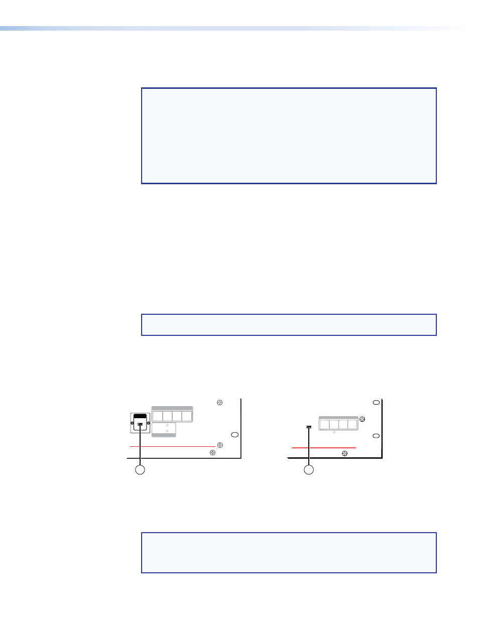
Front Panel Configuration Port
DMS 1600
TMDS DIGITAL MATRIX SWITCHER
POWER SUPPLY
PRIMARY
REDUNDANT
CONTROL
ENTER
PRESET
VIEW
ESC
CONTROL
DMS 2000
TMDS DIGITAL MATRIX SWITCHER
CONFIG
POWER
ENTER
PRESET
VIEW
ESC
CONFIG
1
1
Figure 11.
Front Panel Configuration Port
a
Config(uration) port — This mini USB B port serves a similar communications
function as the rear panel Remote port, but it is easier to access than the rear port after
the matrix switcher has been installed and cabled.
NOTE: A front panel Configuration port connection and a rear panel Remote
port connection can both be active at the same time. If commands are sent
simultaneously to both, the command that reaches the processor first is handled
first.