Reset button and led, Cabling, Rj-45 connector wiring – Extron Electronics DMS 1600_2000_3200_3600 User Guide User Manual
Page 18
DMS 1600, DMS 2000, DMS 3200, and DMS 3600 • Installation
12
Cabling
It is vital that your Ethernet cables be the correct cable type and that they be properly
terminated with the correct pinout. Ethernet links use Category (CAT) 3, 5e, or CAT 6,
unshielded twisted pair (UTP) or shielded twisted pair (STP) cables, terminated with RJ-45
connectors. Ethernet cables are limited to a length of 328 feet (100 m).
NOTES:
•
Do not use standard telephone cables. Telephone cables do not support Ethernet
or Fast Ethernet.
•
Do not stretch or bend cables. Transmission errors can occur.
The cable used depends on your network speed. The switcher supports both
10 Mbps (10Base-T — Ethernet) and 100 Mbps (100Base-T — Fast Ethernet), half-duplex
and full-duplex Ethernet connections.
•
10Base-T Ethernet requires CAT 3 UTP or STP cable at minimum.
•
100Base-T Fast Ethernet requires CAT 5e UTP or STP cable at minimum.
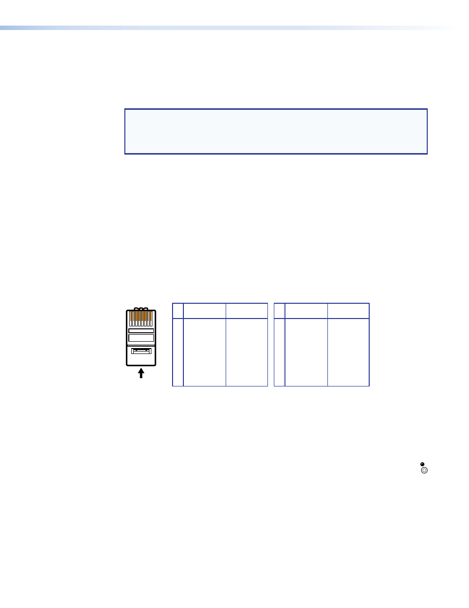
RJ-45 connector wiring
The Ethernet cable can be terminated as a straight-through cable or a crossover cable and
must be properly terminated for your application (see figure 10).
•
Crossover cable — Direct connection between the computer and the DMS matrix
switcher
•
Patch (straight) cable — Connection of the DMS matrix switcher to an Ethernet LAN
A cable that is wired as T568A at one end
and T568B at the other (Tx and Rx pairs
reversed) is a "crossover" cable.
A cable that is wired the same at both ends is
called a "straight-through" cable, because
no pin/pair assignments are swapped.
12345678
RJ-45
Connector
Insert Twisted
Pair Wires
Pins:
Crossover Cable
Straight-through Cable
Pin
1
2
3
4
5
6
7
8
Wire color
White-green
Green
White-orange
Blue
White-blue
Orange
White-brown
Brown
Wire color
T568A
T568B
End 1
End 2
End 1
End 2
White-orange
Orange
White-green
Blue
White-blue
Green
White-brown
Brown
Pin
1
2
3
4
5
6
7
8
Wire color
White-orange
White-green
Blue
White-blue
White-brown
Brown
Wire color
T568B
T568B
White-orange
Orange
Orange
White-green
Blue
White-blue
Green
Green
White-brown
Brown
Figure 10.
RJ-45 Connector and Pinout Tables
Reset Button and LED
g
Reset button — The Reset button initiates four levels of reset of the matrix
RESET
switcher. For four different reset levels, press and hold the button while the
switcher is running or while you power up the switcher (see