Button labels, Rear panel power indicators, Dms 1600 and dms 3600) – Extron Electronics DMS 1600_2000_3200_3600 User Guide User Manual
Page 26
DMS 1600, DMS 2000, DMS 3200, and DMS 3600 • Operation
20
Button Labels
The numbered translucent covers on the input and output buttons can be removed and
replaced to insert labels behind them.
Input and output labels can be created easily with the Extron Button Label Generator
software, which ships with every Extron matrix switcher. Each input and output can be
labeled with names, alphanumeric characters, or color bitmaps for easy and intuitive input
and output selection (see figure 16) (see
Button Label Generator Program
for details on using the labeling software, see
Removing and Installing Button Labels
,
on page 106, for blank labels and a procedure for removing and replacing the translucent
covers).
DVD
VCR
Computer
Computer
Document
Camera
VTG 200
10
13
15
29
28
30 31 32
Figure 16.
Sample Button Labels and Icons
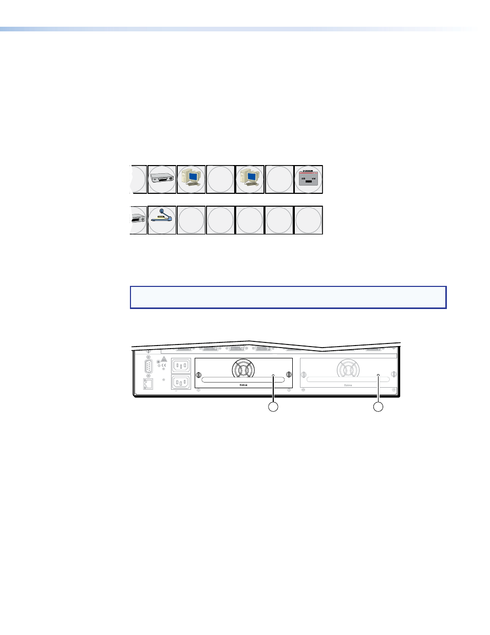
Rear Panel Power Indicators (DMS 1600 and DMS 3600)
NOTE: The DMS 2000 and DMS 3200 each have a built-in, non-removeable power
supply, which does not have the Power Supply LEDs (a), below.
The primary and redundant power supply modules on the DMS 1600 and DMS 3600
(see figure 17) each have a 2-color LED.
RESET
REMO
TE
RS-232/RS-422
LAN
AC
T LINK
100-240V 50/60Hz 1.2A MAX.
100-240V 50/60Hz 1.2A MAX.
REDUND
ANT
PRIMAR
Y
DISCONNECT BO
TH PO
WER
CORDS BEFORE SER
VICING
PRIMARY POWER SUPPLY
REDUNDANT POWER SUPPLY
1
1
1
Redundant Power
Supply is Optional
for DMS 1600, Blank
Panel is Standard
Figure 17.
Rear Panel Power Supply Indicators
a
Primary and Redundant Power Supply LEDs —
Green — Indicates that the associated power supply is operating within normal
tolerances.
Red — Indicates that the associated power supply has failed (see
Installing the Power Supply Module (DMS 1600 and DMS 3600)
, on page 103, to
replace the power supply).