Performing a system reset from the front panel, Background illumination, Performing a system reset from – Extron Electronics DMS 1600_2000_3200_3600 User Guide User Manual
Page 41: The front panel, F (see, Performing a front panel reset, Toggling background illumination on and off
DMS 1600, DMS 2000, DMS 3200, and DMS 3600 • Operation
35
Performing a System Reset from the Front Panel
The front panel reset is identical to the
SIS command on page 56. A system
reset clears all ties and presets, all output mutes, and resets all I/O grouping.
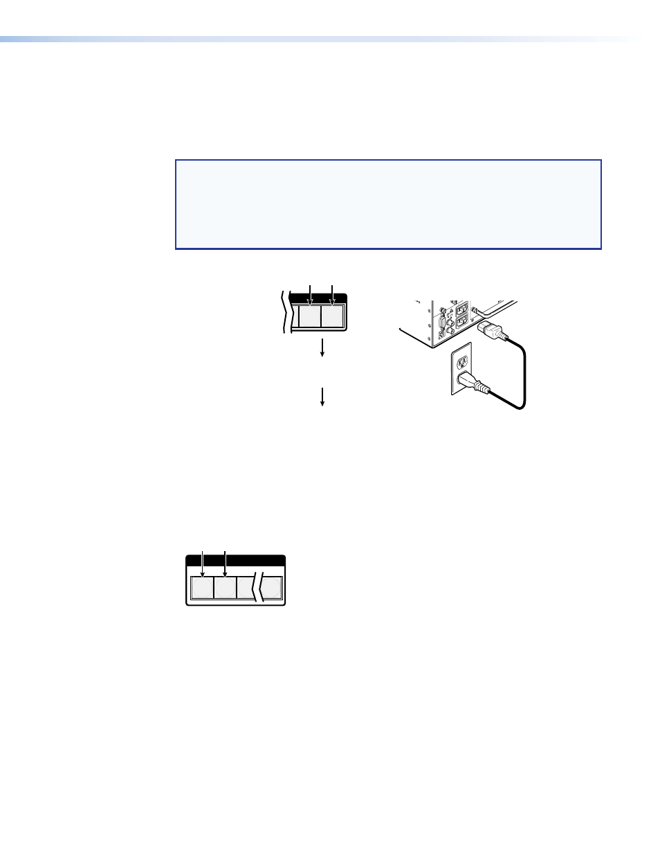
Reset the switcher to the factory default settings by pressing and holding the View button
and Esc button simultaneously while you apply AC power to the switcher (see figure 24).
NOTES:
•
For the reset to occur, you must apply power from an unpowered state. Applying
the redundant power with primary power already applied does not reset the
switcher.
•
System reset does not reset the Internet protocol (IP) settings or replace
user-installed firmware.
CONTROL
T
ESC
VIEW
RESE
T
REMOTE
RS-232/RS-422
LAN
BI-LEVEL
TRI-LEVE
L
ACT LIN
K
100-240V 50/60Hz 1.2A MAX.
100-240V 50/60Hz 1.2A MAX.
REDUNDANT
PRIMAR
Y
DISCONNECT BOTH POWER
CORDS BEFORE SERVICING
SWITCH
REFERENCE
13 - 16
Press and hold the buttons while
you apply power to the switcher.
— and —
Release the View and Esc buttons.
Power
The switcher flashes the
button indicators; light amber,
off, green, red, and amber;
and then turns them off.
Continue to hold the View and Esc
buttons until all input and output buttons
return to either unlit or to background
illumination.
Figure 24.
Performing A System Reset
Background Illumination
The buttons on the front panel can be set to provide amber background illumination at
all times or the background illumination can be turned off. To toggle the background
illumination on or off, press and hold the Input 1 and Input 2 buttons simultaneously for
approximately 2 seconds (see figure 25).
1
2
3 16
Press and hold the buttons.
After approximately 2 seconds, release
the Input 1 and Input 2 buttons.
Figure 25.
Locking the Front Panel