R&M Materials Handling WIRE ROPE HOISTS Service User Manual
Page 92
R&M Materials Handling, Inc.
4501 Gateway Boulevard
Springfield, Ohio 45502
P.: (937) 328-5100
FAX: (937) 325-5319
92/130
R&M Materials Handling, Inc. reserves the right to alter or amend the above information without notice.
• Switch OFF the power supply to the crane.
• Remove the shaft locking parts (8).
• Remove the side plate fixing parts (11)
• Extract the rope sheaves (10), sheave covers (9) and side plates (11).
• Remove the cover plate (7)
• Remove the locking ring (or nut) (6) and thrust bearing (5).
• Extract the hook (3) from the bearing set (4).
Re-assembly:
• Lubricate the thrust bearing and the hook shaft.
• Insert the hook (3) into the bearing house (4) and re-assemble the thrust bearing (5) and the locking
ring (or nut) (6).
1
2
1
2
c_hobeas1a
• Re-assemble the side plates (11), the rope sheaves (10), sheave cover (9) and shaft (8).
• Tighten all fixing screws to the required torque.
• Switch ON the power supply to the crane.
• Raise the hook block. Carefully guide the rope with a gloved hand until the hook block hangs free
from the working platform.
• If the lower limit switch has been adjusted, re-adjust to the correct position.
• Test the operation of the hoist.
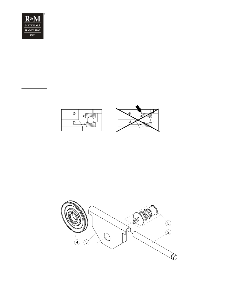
5.29.3 Return sheave assembly
Return sheave, 4-fall, 1-rope reeving, drum size
φ 303/355/406 mm
c_sh04a_000046
2. Shaft
3. Sheave support
4. Rope sheave
5. Shaft set