R&M Materials Handling WIRE ROPE HOISTS Service User Manual
Page 38
R&M Materials Handling, Inc.
4501 Gateway Boulevard
Springfield, Ohio 45502
P.: (937) 328-5100
FAX: (937) 325-5319
38/130
R&M Materials Handling, Inc. reserves the right to alter or amend the above information without notice.
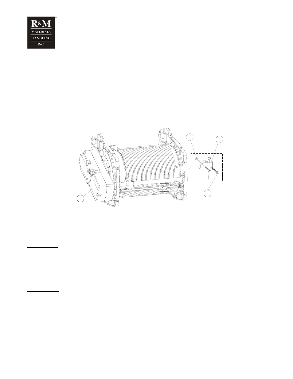
5.13 Hoisting limit switch Drum size
φ 243 mm
The roller lever limit switch unit for hoisting is located under the drum cover, on the limit switch fixing
plate.
5.13.1 Service
• Check the proper tripping point of lower limit function.
• Check that the locking screws (3) are tight.
• Check the wiring for loose connections.
Assembly
c_zlowli01c
2
3
4
1
1. Hoist limit switch
2. Connection box cover
3. Fixing screws for limit switch
4. Fixing nut
Disassembly:
• Switch OFF the power supply to the hoist.
• Remove the connection-box cover (2).
• Remove the wires from the limit switch connector in the connection-box.
• Remove the fixing screws (3).
• Extract the limit switch (1).
Re-assembly:
• Fit the limit switch carefully in its place, so that the roller lever is in correct position and in front of the
limit switch fixing plate.
• Tighten the fixing screws (3)
• Re-connect the wires.
• Switch ON the power supply to the hoist and check the proper functioning of the limit switch.
!
In many cases it is necessary to re-adjust the limit switch. Be aware of incorrect settings
during testing the operation.