R&M Materials Handling WIRE ROPE HOISTS Service User Manual
Page 107
R&M Materials Handling, Inc.
4501 Gateway Boulevard
Springfield, Ohio 45502
P.: (937) 328-5100
FAX: (937) 325-5319
107/130
R&M Materials Handling, Inc. reserves the right to alter or amend the above information without notice.
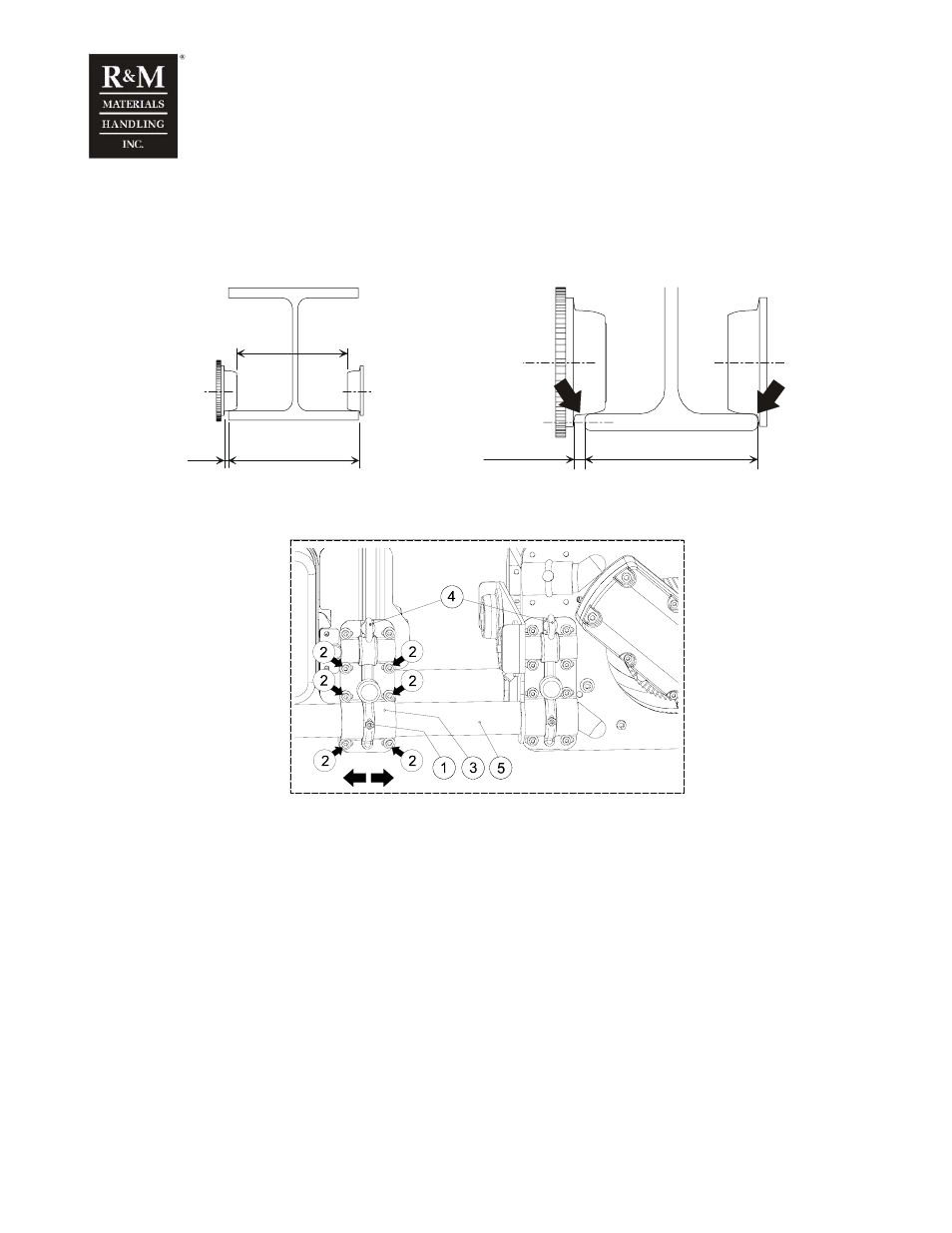
6.3 Low headroom trolley
When installing a low headroom trolley, the wheel gauge has to be adjusted properly. Clearance between
the wheel flange and the main girder flange (measure X) must be 3…5 mm. Ensure that the clearance is
equal on both ends of the trolley.
c_lab1b
B
X
A
B
X
Drum size
φ 303mm
c_bmla1a
1. Locking screw and nut
2. Fixing screws for fixing bracket
3. Fixing bracket
4. Lifting lugs for raising the hoist
5. Frame tube
• Remove the temporary transport supports. Take the hoist out of the packing and move it to the
installation site. Lift the hoist using the lifting lugs (4).
• Loosen the locking (1) on frame tubes of the trolley drive side. Loosen the lowest fixing screws (2) for
the fixing brackets. Adjust the distance between the travel wheels (A) so that it is slightly wider than
the beam flange (B) for installation purposes.
!
Do not unscrew the fixing screws for the fixing bracket on the hoisting machinery side!
• Lift the hoist onto the beam. Adjust the X measurement until there is a gap of approximately 3…5mm
between the flange of the travel wheels and the flange of the beam. Use a nylon mallet to adjust the X
measurement.
• Check the wheels of the trolley are correctly aligned.