R&M Materials Handling WIRE ROPE HOISTS Service User Manual
Page 56
R&M Materials Handling, Inc.
4501 Gateway Boulevard
Springfield, Ohio 45502
P.: (937) 328-5100
FAX: (937) 325-5319
56/130
R&M Materials Handling, Inc. reserves the right to alter or amend the above information without notice.
5.21.2 Dismounting the travelling motor
• Ensure there is no danger of live voltage.
• Remove the power supply plug (8) for the travelling machinery.
• Unscrew the fixing screws (3) for the motor.
• Detach the motor from the gearbox.
• Re-assemble in the reverse sequence
5.22 Inverter for travel
The electrical cubicle on the hoist contains a inverter that controls the speed of rotation of the travelling
motor, according to the commands given by the operator.
The inverter has a signal LEDs (2) indicating its operating status and eventual malfunction.
The parameters of the inverter are pre-set at the factory, and usually do not require re-adjustment. In
case re-adjustment is needed, please refer to the Service Manual of the respective inverter for details, or
contact a representative of the manufacturer.
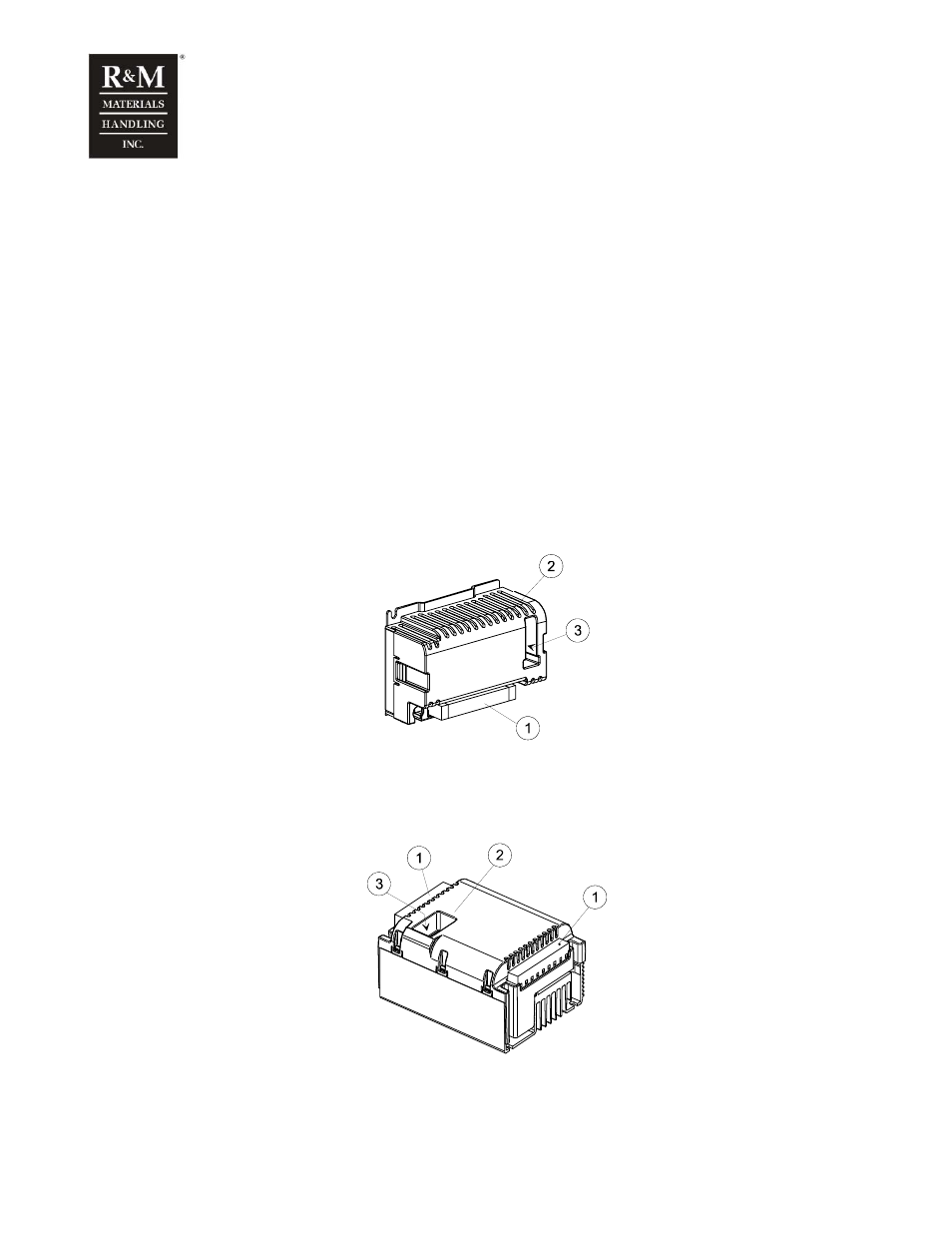
All electrical connections to the inverter are made via connector(s) (1).
0,7kW inverter
c_fc007a
1. Connectors
2. Signal LEDs
3. Parameter switches
2,2kW inverter
c_fc022a
1. Connectors
2. Signal LEDs
3. Parameter switches