R&M Materials Handling WIRE ROPE HOISTS Service User Manual
Page 28
R&M Materials Handling, Inc.
4501 Gateway Boulevard
Springfield, Ohio 45502
P.: (937) 328-5100
FAX: (937) 325-5319
28/130
R&M Materials Handling, Inc. reserves the right to alter or amend the above information without notice.
-
Drive pinion of the gear fits correctly into the gear-rim of the drum. Rotate the motor’s shaft on the brake-end
side to guide the pinion into the gear-rim and to check the right fitting.
• Fasten the bolts B & D.
• Remove the thread bars and fasten the bolts A & C.
• Tighten the bolts to the correct torque.
• Re-assemble the hoist limit switch.
• Insert the brake wires into the plug and re-connect the power feed connector.
• Tighten the brake fixing screws.
• Remove the drum-locking device (wooden wedge).
• Re-assemble the protective cover of the hoisting machinery.
• Test the proper operation of all movements and functions
!
In many cases it is necessary to re-adjust the limit switch. Be aware of incorrect settings
during testing the operation.
Drum size ø 608 mm
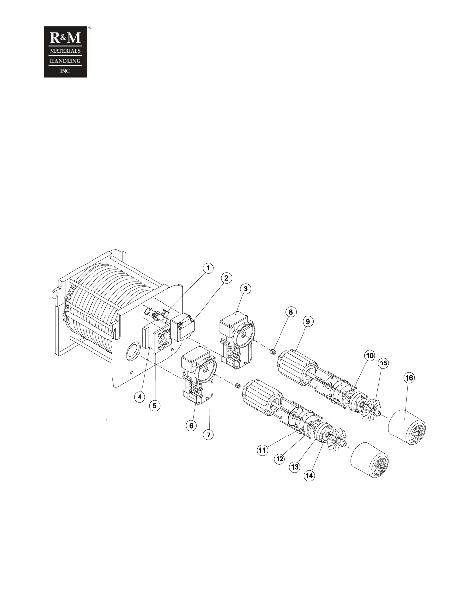
In the models with drum size ø 608mm, the motor(s) can be extracted from the gearbox separately.
c_r3hm1c
1. Hoisting limit switch
2. Cover hoisting limit switch
3. Connection box
4. Drum-bearing house
5. Fixing plate for gearbox
6. Fixing screws for gearbox
7. Hoisting gearbox
8. Coupling.