Figure 5.6: integration time configuration area, Figure 5.6:integration time configuration area – B&B Electronics ADAM-6066 - Manual User Manual
Page 84
ADAM-6000 Series User Manual
74
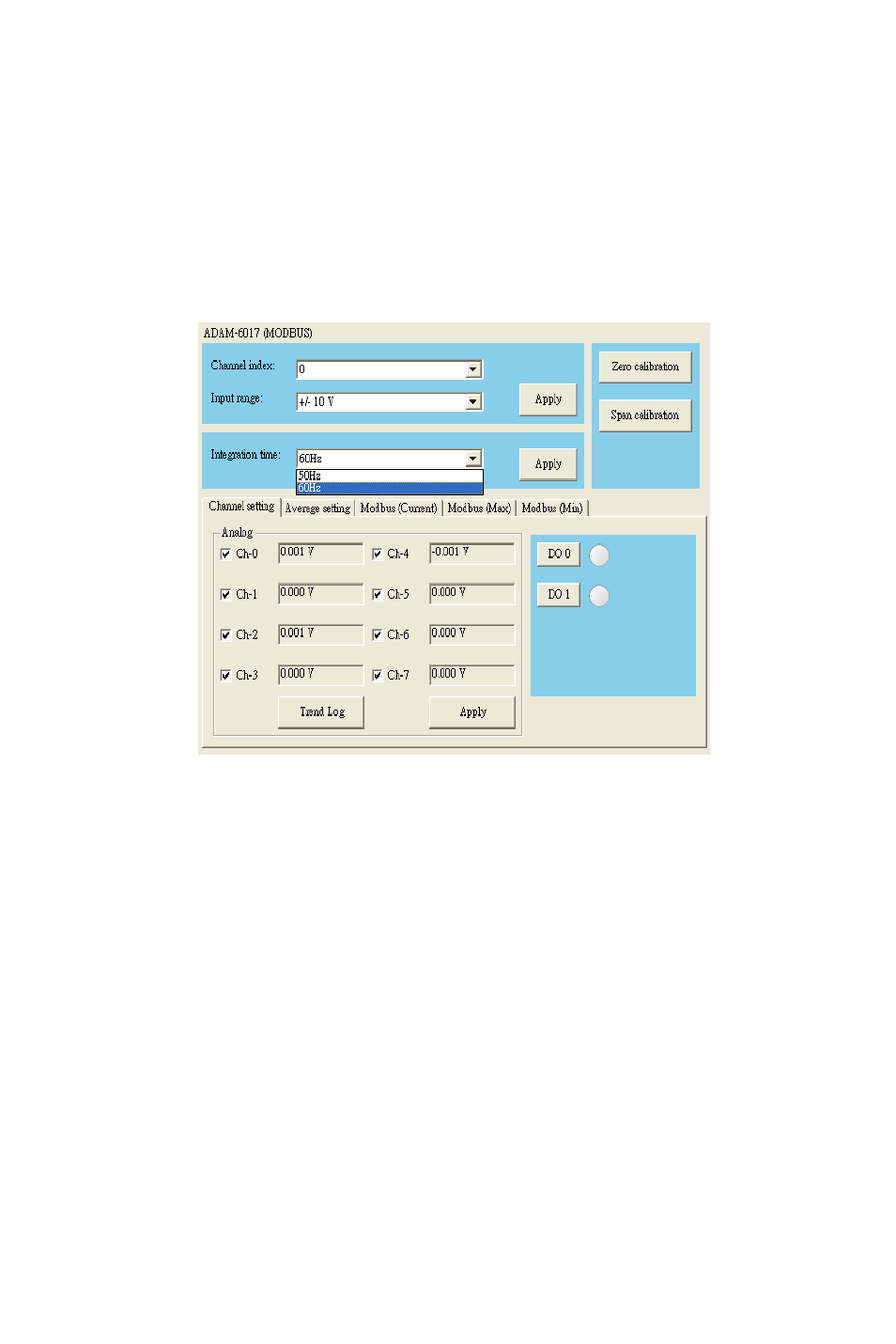
In order to remove the noise from the power supply, these analog input
modules feature built-in filter. Two filters with different frequencies are
provided to remove noise generated from different power supplies. The
Integration Time Configuration area is under the Channels Range
Configuration area. Refer to Figure 5.6 below. In the Integration Time
Configuration area, you can select suitable filter in the Integration time
combo box. After selecting appropriate filter, click the Apply button.
Figure 5.6: Integration Time Configuration Area
In the top right-hand corner of the Status Display area is the Calibration
area. You can choose the Zero Calibration button to do zero calibration.
After you click the button, a pop-up dialog window will remind you to
connect a signal with minimum value of full scale range (for example, 0
Volt) to the calibrated channel. After you complete the hardware wiring,
click the Apply button to start the calibration action. Similarly, you can
choose the Span Calibration button to do span calibration. For span cal-
ibration, you need to connect a signal with maximum value of full scale
range (for example, 10 Volt) to the calibrated channel. It is the same that
when you complete the wiring, click the Apply button to start the calibra-
tion action.