2 logic stage, Figure 7.6: logic stage configuration, Logic stage figure 7.6:logic stage configuration – B&B Electronics ADAM-6066 - Manual User Manual
Page 192
ADAM-6000 Series User Manual
182
7.3.2 Logic Stage
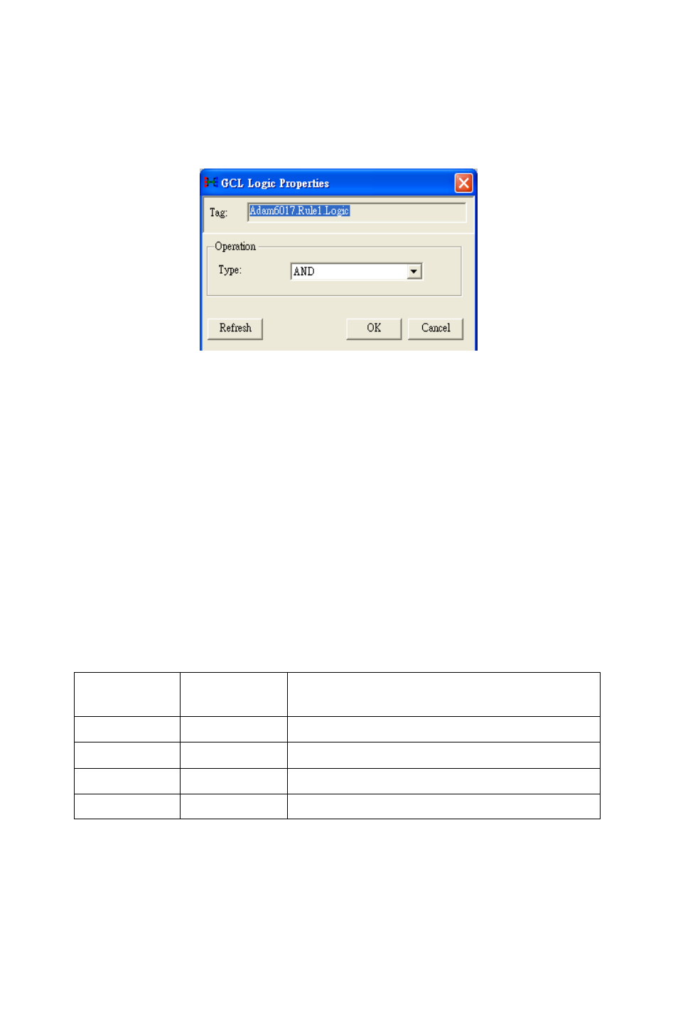
When you click the Logic stage icon, you should see a dialog window
similar to Figure 7.6 below.
Figure 7.6: Logic Stage Configuration
For each logic rule, there will be at most three input conditions passing
logic True or False values to the Logic stage here. You can choose four
logic operations by the Type combo box: AND, OR, NAND, NOR. The
logic operation will process the input logic values, and generate a logic
result value to the next Execution stage. After you have selected the
appropriate logic operation, click the OK button. The Logic stage icon
will change its pattern to present the current logic operation.
In order to present how the four logic operations work, we use the truth
table to describe. Here we take two input conditions as example. The let-
ter “T” means logic True, while the letter “F” means logic False.
AND
Input
Condition 1
Input
Condition 2
Logic value to the Execution Stage
F
F
F
F
T
F
T
F
F
T
T
T