Figure 7.2: four stages for one logic rule, Figure 7.2:four stages for one logic rule – B&B Electronics ADAM-6066 - Manual User Manual
Page 183
173
Chapter 7
Below the GCL Menu area is the Logic Rule Set area. There are 16 logic
rules available on one ADAM-6000 module, so you can see 16 logic rule
icons here. Simply click the logic rule icon to configure that rule. For
example, if you want to configure rule 12, just click the logic rule icon
with text “Rule 12” below. The text background color of the selected
logic rule icon will become green.
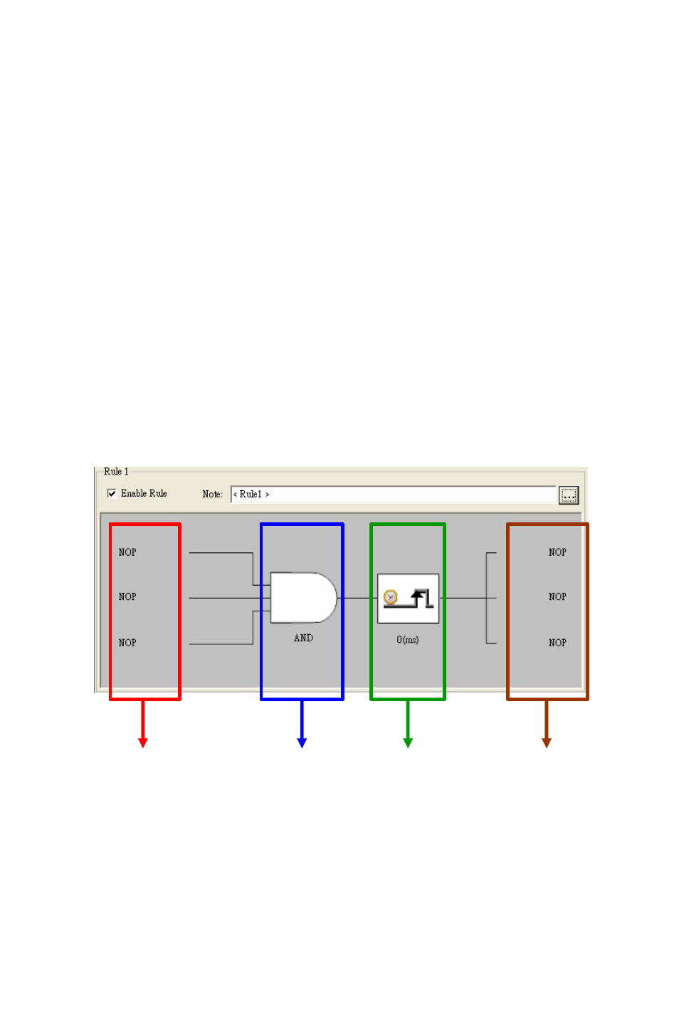
At the bottom of the Status Display area is the Individual Logic Rule
Configuration area. After you have selected the rule you want to config-
ure in the Logic Rule Set area, click the Enable Rule check box to
enable that logic rule. The color of that logic rule icon will become white
after you enable it. You can write some description for that logic rule by
clicking the button next to the Note text box. There are four stages for one
logic rule:
Input Condition
,
Logic
,
Execution
and
Output
, which are all
displayed by graphical icon in the Individual Logic Rule Configuration
area. Refer to Figure 7.2 below. You can simply click the graphical icon
to configure each stage and one related configuration window will pop-
up.
Figure 7.2: Four Stages for One Logic Rule
Input Condition Stage
Logic Stage
Execution Stage
Output Stage