B.2.8 adam-6060/6060w/6066, Ch di & relay module – B&B Electronics ADAM-6066 - Manual User Manual
Page 255
245
Appendix B
4.
When DI channel is configured as “High to low latch” or “Low to
high latch”, this bit will be 1 if the latch condition occurs. After
that, value of this bit will keep 1 until user writes 0 to this bit (clear
the latch status).
5.
Decide how many pulses will be generated. When user writes 0 to
this bit, it will continuously generate pulse.
6.
During the pulse generation, user can use this bit to generate more
pulses. For example, “Absolute pulse” is set as 100. During its gen-
eration, user can set “Incremental pulse” as 10. After the 100 pulses
are generated, the extra 10 pulses will continue to be generated.
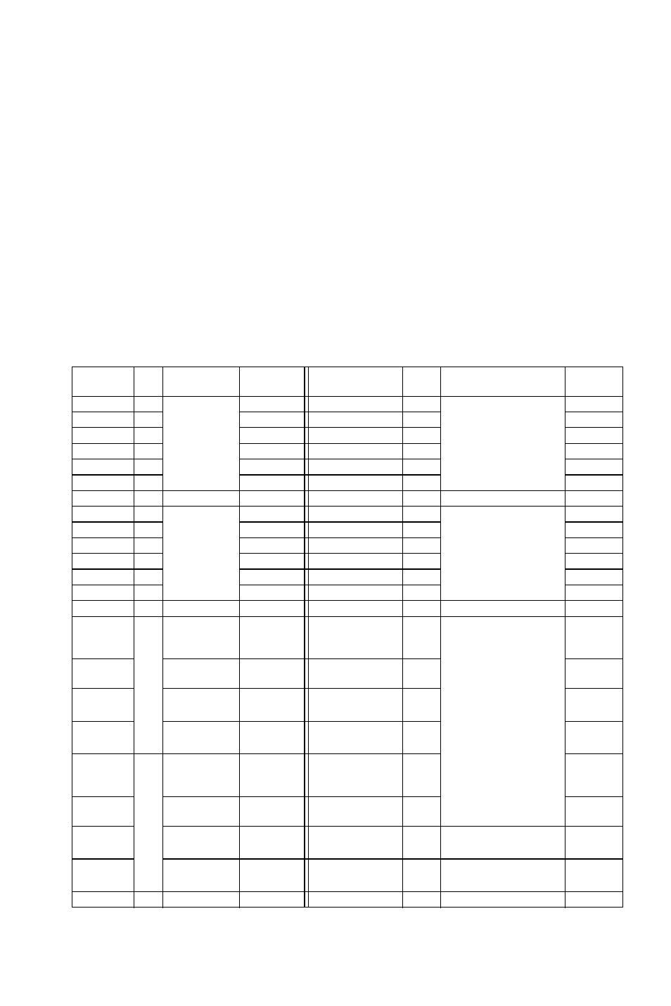
B.2.8 ADAM-6060/6060W/6066
12-ch DI & Relay Module
Address
0X
Ch Description Attribute Address 4X
Ch
Description
Attribute
00001 0 DI
Value
Read 40001~40002
0 Counter/Frequency
Value
1
Read
00002 1
Read 40003~40004
1
Read
00003 2
Read 40005~40006
2
Read
00004 3
Read 40007~40008
3
Read
00005 4
Read 40009~40010
4
Read
00006 5
Read 40011~40012
5
Read
00017
0
DO Value
R/W
40013~40014 0
Pulse Output
Low Level Width
2
R/W
00018 1
R/W
40015~40016
1
R/W
00019 2
R/W
40017~40018
2
R/W
00020 3
R/W
40019~40020
3
R/W
00021 4
R/W
40021~40022
4
R/W
00022 5
R/W
40023~40024
5
R/W
00033 0 Counter
Start(1)/
Stop(0)
R/W
40025~40026 0
Pulse
Output
High Level Width
2
R/W
00034 Clear
Coun-
ter(1)
Write 40027~40028
1
R/W
00035 Clear
Overflow
3
R/W 40029~40030
2
R/W
00036 DI
Latch
Status
4
R/W
40031~40032 3
R/W
00037 1 Counter
Start(1)/
Stop(0)
R/W
40033~40034 4
R/W
00038 Clear
Coun-
ter(1)
Write 40035~40036
5
R/W
00039 Clear
Overflow
3
R/W
00040 DI
Latch
Status
4
R/W
40037~40038 0
Set Absolute Pulse
5
R/W