Figure 7.30: gcl logic for flicker, Figure 7.31: time chart for rising edge – B&B Electronics ADAM-6066 - Manual User Manual
Page 219
209
Chapter 7
We need to use 1 Internal Flag (Flag 0) and 2 logic rules for the Flicker
application described above. In logic rule 1, the value of Flag 0 is
inverted (By choosing NAND in the Logic stage) periodically. (Here, it is
0.5 second) The period is defined by the Execution_Period in the Execu-
tion Stage. (Refer to the Section 7.3.3) The status of DO 0 is controlled
by Flag 0 in logic rule 2, so DO 0 will change every 0.5 second. The GCL
logic rule architecture is shown by Figure 7.30 below:
Figure 7.30: GCL Logic for Flicker
6.
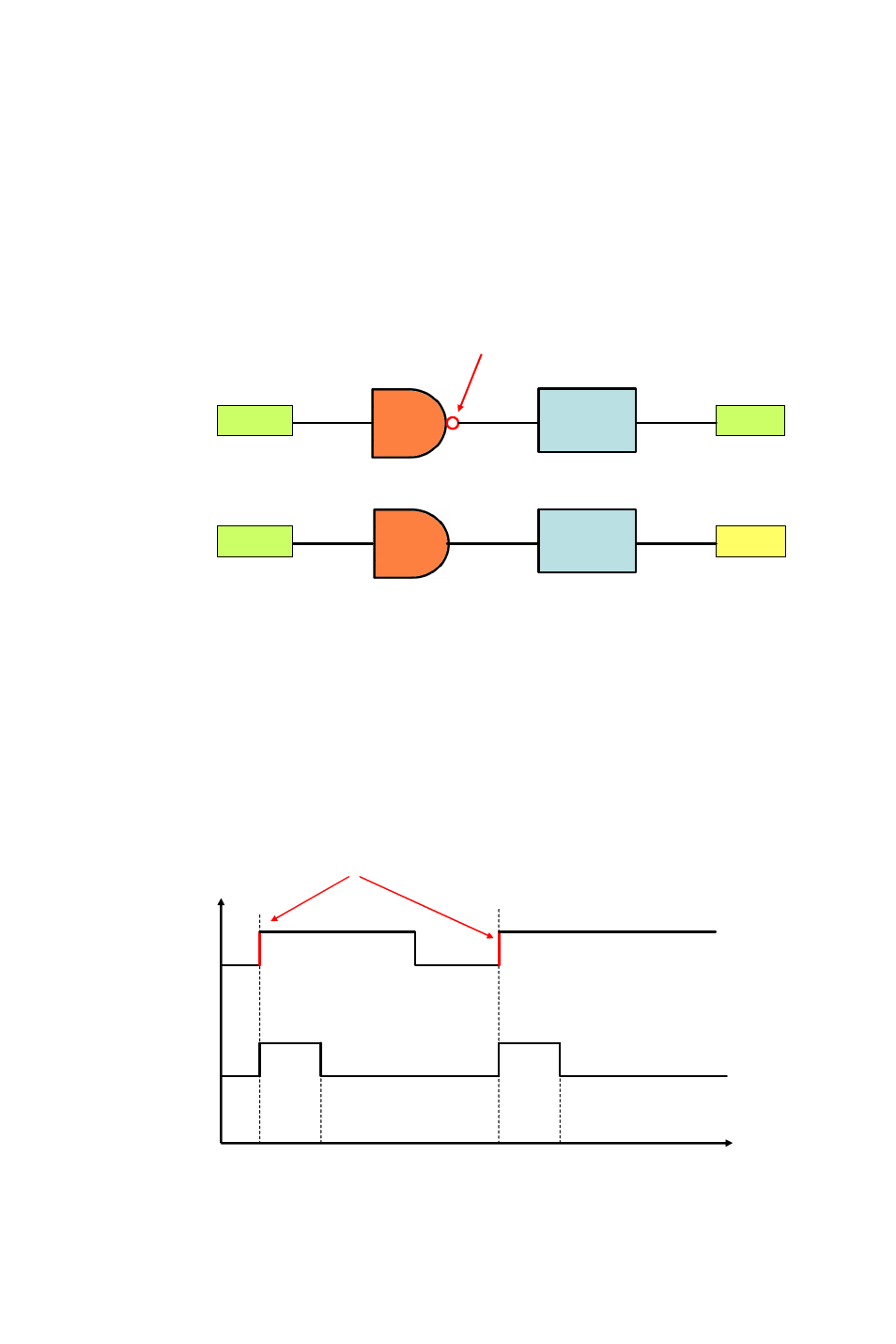
Rising Edge
For Rising Edge application, the DO status will be activated to logic high,
when DI value is changed from logic low to logic high (it is so-called ris-
ing edge). But the DO value won’t continuously remain logic high.
Instead, after a specific time interval (in the example, it is 1 second), the
DO value will return to logic low. Refer below for its time chart:
Figure 7.31: Time Chart for Rising Edge
AND
Flag 0
DO 0
AND
Flag 0
Rule 1
Rule 2
Period
500 ms
Inverse
Flag 0
Period
0 ms
DO 0
Time
T0
T1
T0 + 1 second
T1 + 1 second
DI 0
Rising Edge