Figure 7.38: gcl logic for sequence control, Figure 7.38:gcl logic for sequence control – B&B Electronics ADAM-6066 - Manual User Manual
Page 224
ADAM-6000 Series User Manual
214
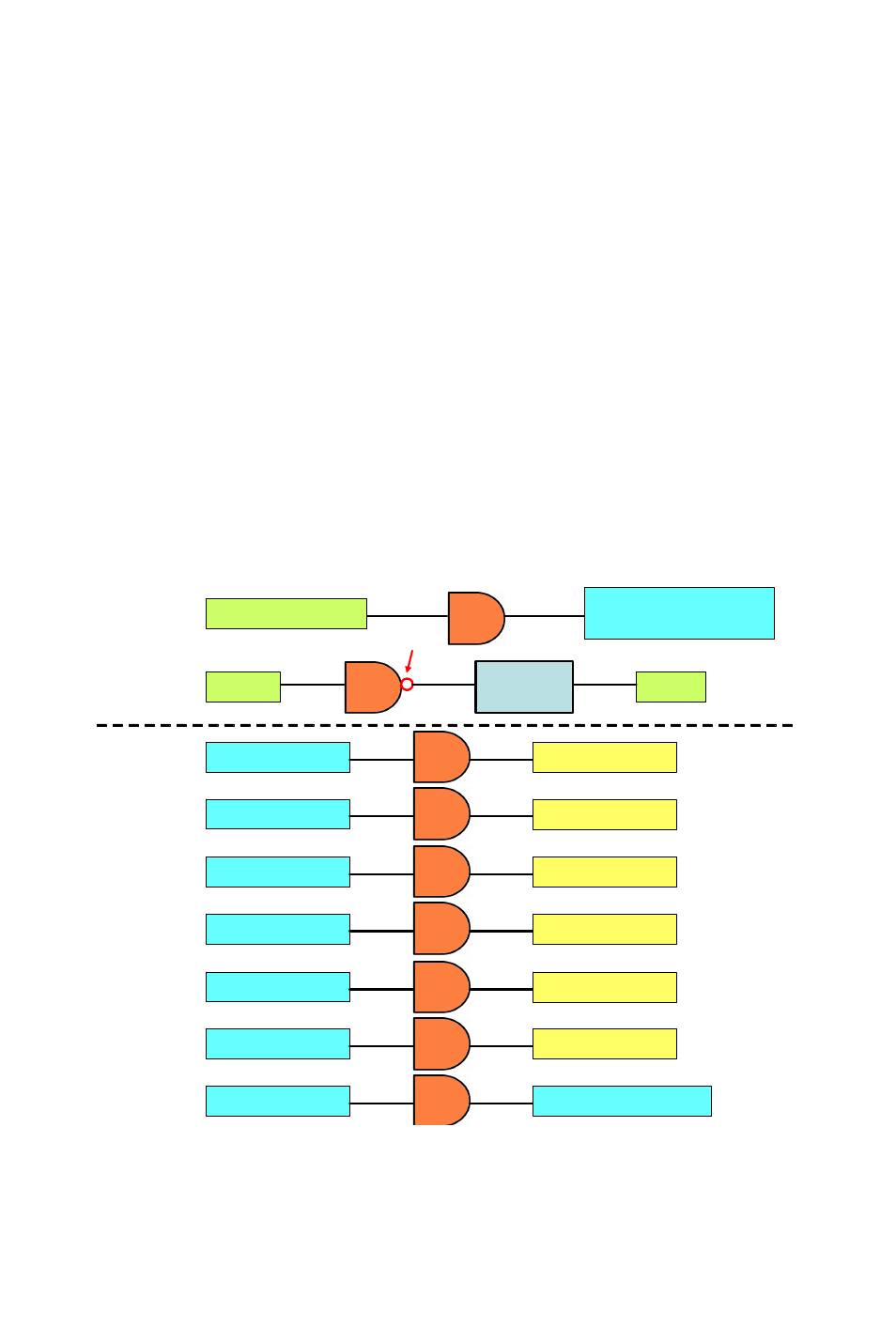
In order to implement this kind of application, 9 logic rules, 1 Internal
Counter (Counter 0) and 1 Internal Flag (Flag 0) are used. In the example
project we provide, logic rule 1 and 8 are used to create the time base. By
logic rule 8, Flag 0 value will change every 0.5 second. In logic rule 1,
once the Flag 0 value is logic high, the Counter 0 will increase 1 unit. So
every 1 second, Counter 0 will increase 1 unit, making Counter 0 the time
base.
Logic rules 9 ~ 14 are used to control DO 0 ~ 5. Which logic rule should
be executed is based on Counter 0 value. Since Counter 0 value will con-
tinuously add 1 unit every 1 second, logic rules 9 ~ 14 will be executed in
sequence every 1 second. Therefore, DO 0 ~ DO 5 will be activated
sequentially in 1 second. When logic rule 15 is executed, Counter 0 will
reset and its value will back to zero. So it makes the logic rules execution
become a continuous loop. Refer to Figure 7.38 below for its GCL archi-
tecture.
Figure 7.38: GCL Logic for Sequence Control
(Turn On and Off in Sequence Continuously)
AND
Increase 1 Count of
Internal Counter 0
If Flag 0 = True
Rule 1
Rule 8
AND
Flag 0
Flag 0
Period
500 ms
Inverse
If Counter 0 = 1
AND
Set DO 0 =True
Rule 9
If Counter 0 = 2
AND
Set DO 1 =True
Rule 10
If Counter 0 = 3
AND
Set DO 2 =True
Rule 11
If Counter 0 = 4
AND
Set DO 3 =True
Rule 12
If Counter 0 = 5
AND
Set DO 4 =True
Rule 13
If Counter 0 = 6
AND
Set DO 5 =True
Rule 14
If Counter 0 = 7
AND
Reset Counter 0
Rule 15