Flight instruments, Gps cdi scaling – Garmin G1000 King Air C90GT User Manual
Page 85
190-00663-01 Rev. A
Garmin G1000 Pilot’s Guide for the Hawker Beechcraft C90A/GT
71
FLIGHT INSTRUMENTS
SY
STEM
O
VER
VIEW
FLIGHT
INSTRUMENTS
EIS
AUDIO P
ANEL
& CNS
FLIGHT
MANA
GEMENT
HAZARD
AV
OID
ANCE
AFCS
ADDITIONAL
FEA
TURES
APPENDICES
INDEX
GPS steering guidance is still provided after the CDI automatically switches to LOC until LOC capture, up
to the Final Approach Fix (FAF) for an ILS approach, or until GPS information becomes invalid. Activating
a Vector-to-Final (VTF; see the Flight Management Section) also causes the CDI to switch to LOC navigation
source; GPS steering guidance is not provided after this switch.
GPS CDI SCALING
When GPS is the selected navigation source, the flight plan legs are sequenced automatically and
annunciations appear on the HSI for the flight phase. Flight phase annunciations are normally shown in
magenta, but when cautionary conditions exist the color changes to yellow. If the current leg in the flight plan
is a heading leg, ‘HDG LEG’ is annunciated in magenta beneath the aircraft symbol.
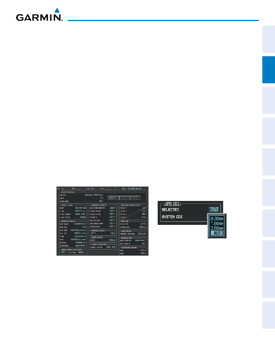
The current GPS CDI scale setting is displayed as ‘System CDI’ on the AUX - System Setup Page and the full-
scale deflection setting may also be changed (2.0 nm, 1.0 nm, 0.3 nm, or Auto) from this page (Figure 2-30).
If the selected scaling is smaller than the automatic setting for enroute and terminal phases, the CDI is scaled
accordingly and the selected setting is be displayed rather than the flight phase annunciation.
Changing the selected GPS CDI setting:
1)
Use the FMS Knob to select the AUX - System Setup Page on the MFD.
2)
Press the FMS Knob to activate the cursor.
3)
Turn the large FMS Knob to highlight ‘Selected’ in the ‘GPS CDI’ box.
4)
Turn the small FMS Knob to highlight the desired setting and press the ENT Key.
5)
To cancel the selection, press the FMS Knob or the CLR Key.
Figure 2-29 System Setup Page, GPS CDI Settings
When set to ‘Auto’ (default), the GPS CDI scale automatically adjusts to the desired limits based upon the
current phase of flight (Figure 2-30, 2-31, 2-32, Table 2-2).