Hazard avoidance – Garmin G1000 King Air C90GT User Manual
Page 347
190-00663-01 Rev. A
Garmin G1000 Pilot’s Guide for the Hawker Beechcraft C90A/GT
333
HAZARD AVOIDANCE
SY
STEM
O
VER
VIEW
FLIGHT
INSTRUMENTS
EIS
AUDIO P
ANEL
& CNS
FLIGHT
MANA
GEMENT
HAZARD
AV
OID
ANCE
AFCS
ADDITIONAL
FEA
TURES
APPENDICES
INDEX
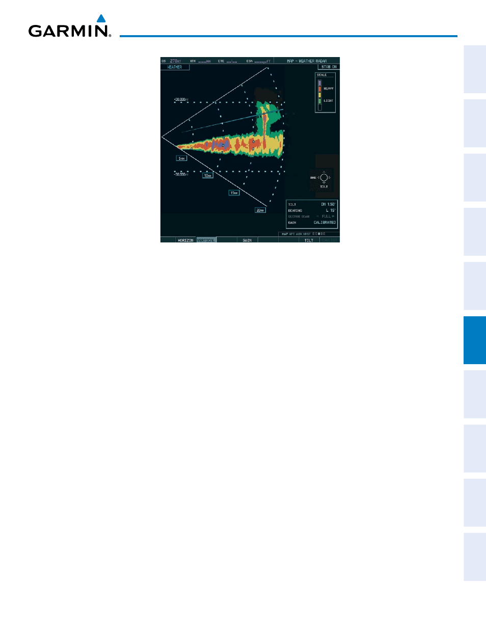
Figure 6-56 Vertical Scan Display
a
DjUsting
a
ntenna
t
ilt
a
ngle
In order to make an accurate interpretation of a storm cell, the radar beam should be pointed at the wet
part of the weather cell to record the proper rainfall intensity (color level). The ideal aiming point is just
below the freezing level of the storm. The best way to find this point is to use the Vertical Scan feature. The
antenna tilt angle can be centered on the strongest return area in the vertical scan to get a more accurate
view of the coverage and intensity of the target in the horizontal scan.
Adjusting antenna tilt on the Horizontal Scan display:
1)
Press the FMS Knob to activate the cursor in the TILT field.
2)
Turn the small FMS Knob to select the desired antenna tilt angle.
3)
Press the ENT Key.
4)
Press the FMS Knob to remove the cursor.
The RANGE Knob can also be used to adjust tilt up and down.
Adjusting antenna tilt on the Vertical Scan display:
1)
Select the TILT Softkey to activate the cursor in the TILT field and display the Tilt Line.
If the Tilt Line is not displayed, press the MENU Key and turn the large FMS Knob to select Show Tilt Line. Press
the ENT Key.
2)
Turn the small FMS Knob to adjust the antenna tilt angle. The selected tilt angle is implemented when Horizontal
Scan is again selected.
The RANGE Knob can also be used to adjust tilt.