System overview – Garmin G1000 King Air C90GT User Manual
Page 17
190-00663-01 Rev. A
Garmin G1000 Pilot’s Guide for the Hawker Beechcraft C90A/GT
3
SYSTEM OVERVIEW
SY
STEM
O
VER
VIEW
FLIGHT
INSTRUMENTS
EIS
AUDIO P
ANEL
& CNS
FLIGHT
MANA
GEMENT
HAZARD
AV
OID
ANCE
AFCS
ADDITIONAL
FEA
TURES
APPENDICES
INDEX
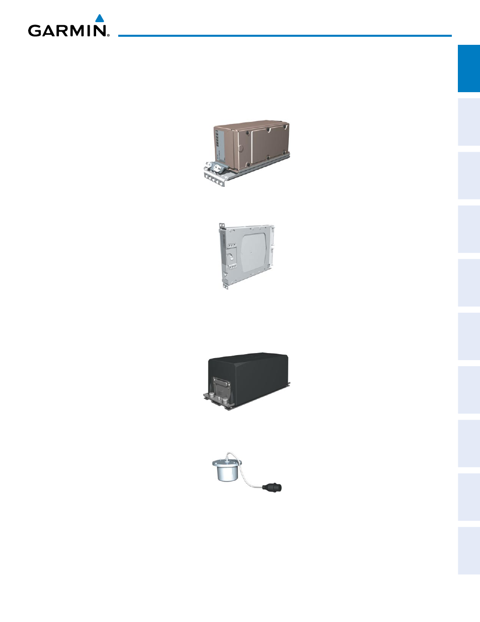
• GDC 74B (2) – Processes data from the pitot/static system as well as the OAT probe. This unit provides
pressure altitude, airspeed, vertical speed and OAT information to the G1000 system, and it communicates
with the on-side GIA 63W, on-side GDU 1040A, GDU 1040A MFD, and on-side GRS 77, using an ARINC 429
digital interface (it also interfaces directly with the on-side GTP 59). The GDC 74B is designed to operate in
Reduced Vertical Separation Minimum (RVSM) airspace.
• GEA 71 (2) – Receives and processes signals from the engine and airframe sensors. This unit communicates
with both GIA 63Ws using an RS-485 digital interface.
• GRS 77 (2) – Provides aircraft attitude and heading information via ARINC 429 to both the on-side GDU
1040A, the GDU 1040A MFD, and the on-side GIA 63W. The GRS 77 contains advanced sensors (including
accelerometers and rate sensors) and interfaces with the on-side GMU 44 to obtain magnetic field information,
with the GDC 74B to obtain air data, and with both GIA 63Ws to obtain GPS information. AHRS modes of
operation are discussed later in this document.
• GMU 44 (2) – Measures local magnetic field. Data is sent to the GRS 77 for processing to determine aircraft
magnetic heading. This unit receives power directly from the GRS 77 and communicates with the GRS 77,
using an RS-485 digital interface.