NEC PD754144 User Manual
Page 189
CHAPTER 7 INTERRUPT AND TEST FUNCTIONS
189
User’s Manual U10676EJ3V0UM
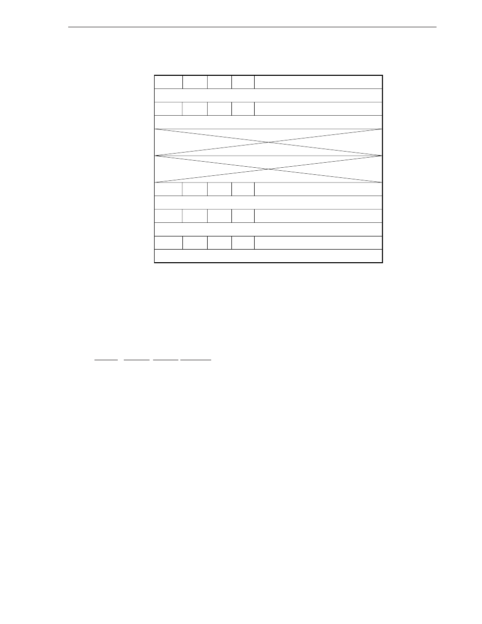
Figure 7-2. Interrupt Vector Table
MBE
MBE
MBE
MBE
MBE
Address
0002H
0004H
0006H
0008H
000AH
000CH
000EH
RBE
RBE
RBE
RBE
RBE
INTBT start address (higher 4 bits)
INTBT start address (lower 8 bits)
INT0 start address (higher 4 bits)
INT0 start address (lower 8 bits)
INTT0 start address (higher 4 bits)
INTT0 start address (lower 8 bits)
INTT1, INTT2 start address (higher 4 bits)
INTT1, INTT2 start address (lower 8 bits)
INTEE start address (higher 4 bits)
INTEE start address (lower 8 bits)
0
0
0
0
0
0
0
0
0
0
The priority column in Table 7-1 indicates the priority according to which interrupts are executed if two or more
interrupts occur at the same time, or if two or more interrupt requests are held pending.
Write the start address of interrupt servicing to the vector table , and the set values of MBE and RBE during interrupt
servicing. The vector table is set by using an assembler quasi directive (VENTn: n = 1, 2, or 5 to 7).
Example Setting of vector table of INTBT
VENT1 MBE=0, RBE=0, GOTOBT
↑
↑
↑
↑
<1>
<2>
<3>
<4>
<1> Vector table of address 0002
<2> Setting of MBE in interrupt servicing routine
<3> Setting of RBE in interrupt servicing routine
<4> Symbol indicating start address of interrupt servicing routine
Caution The contents described as the operand of VENTn (n = 1, 2, or 5 to 7) (MBE, RBE, or start address)
are stored in the vector table address at address 2n.
Example Setting of vector tables of INTBT and INTT0
VENT1 MBE=0, RBE=0, GOTOBT; INTBT start address
VENT5 MBE=0, RBE=1, GOTOT0; INTT0 start address