NEC PD754144 User Manual
Page 111
CHAPTER 6 PERIPHERAL HARDWARE FUNCTION
111
User’s Manual U10676EJ3V0UM
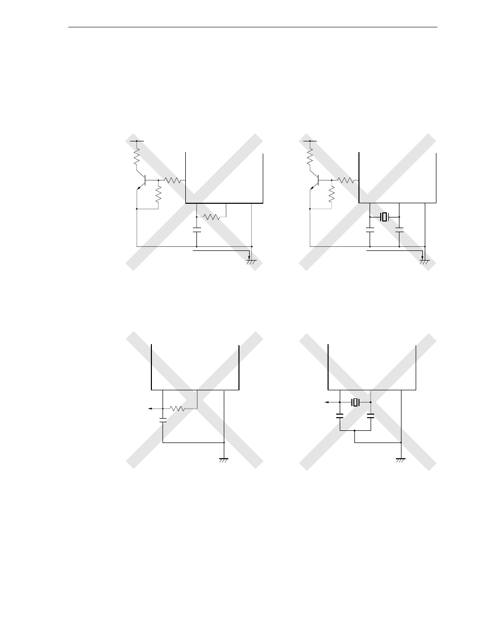
Figure 6-18. Example of Incorrect Resonator Connection (3/3)
(d) Current flowing through power line of oscillator
(potential at points A, B, and C changes)
µPD754144
CL1
CL2
V
SS
PORTn
(n = 3, 6-8)
V
DD
A
B
High current
µ
• PD754144
µ
• PD754244
µPD754244
X1
X2
V
SS
PORTn
(n = 3, 6-8)
V
DD
A
C
High current
B
(e) Signal fetched
µPD754144
CL1
CL2
V
SS
µ
• PD754144
µ
• PD754244
µ PD754244
X1
X2
V
SS
(3) Divider circuit
The divider circuit divides the output of the system clock oscillator to create various clock signals.
This manual is related to the following products: