NEC PD754144 User Manual
Page 146
CHAPTER 6 PERIPHERAL HARDWARE FUNCTION
146
User’s Manual U10676EJ3V0UM
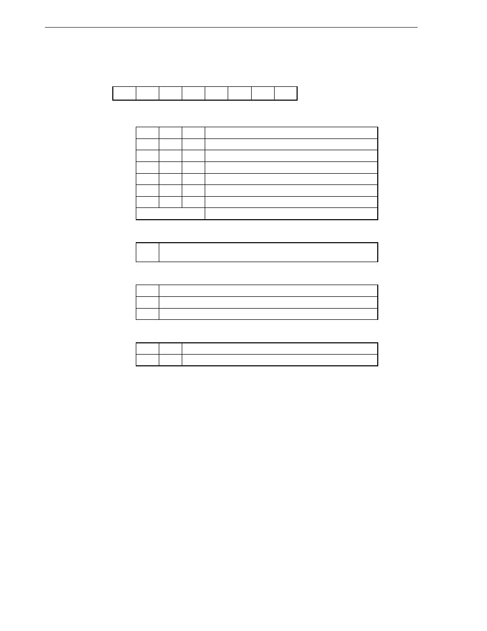
Figure 6-36. Setting of Timer Counter Mode Register
7
6
5
4
3
2
1
0
TM20
TM21
TM23
TM22
TM24
TM25
TM26
–
Address
TM2
F90H
Symbol
TM23
Clears counter and IRQT2 flag when "1" is written. Starts count operation
if bit 2 is set to "1".
Timer start command bit
Operation mode
TM22
0
1
Stops (count value retained)
Count operation
Count operation
Count pulse (CP) select bit
TM26
Count pulse (CP)
TM25
0
1
1
0
0
1
1
0
TM24
0
1
0
1
1
1
0
1
1
1
Operation mode select bit
TM21
0
PWM pulse generator mode
Mode
TM20
1
f
X
/2
f
X
f
X
/2
8
f
X
/2
6
f
X
/2
10
f
X
/2
4
Other
Setting prohibited
Remark
When the timer counter (channel 2) is used as the PWM pulse generator mode, set the operation mode
select bits TM10 and TM11 of the time counter (channel 1) to 0.
This manual is related to the following products: