NEC PD754144 User Manual
Page 113
CHAPTER 6 PERIPHERAL HARDWARE FUNCTION
113
User’s Manual U10676EJ3V0UM
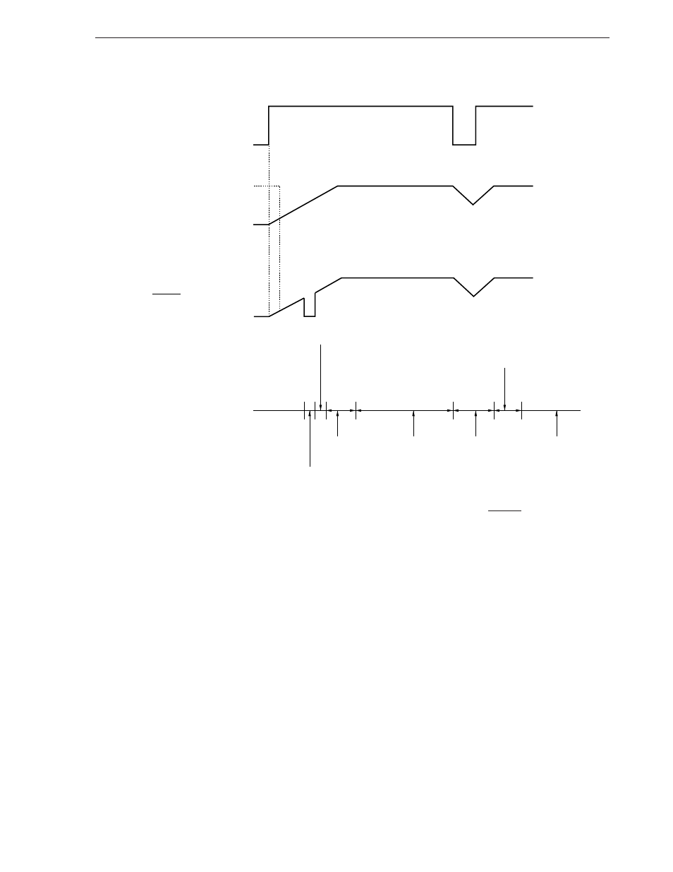
Figure 6-19. CPU Clock Switching Example
<1> Wait time
Note 1
to secure the oscillation stabilization time in response to RESET signal generation.
<2> The CPU starts operating at the lowest system clock speed
Note 2
.
<3> The PCC is rewritten and the device operates at maximum speed after the elapse of sufficient time
for the V
DD
pin voltage to increase to a level which allows maximum speed operation.
<4> Interruption of the commercial power is detected by means of interrupt input, etc., and the STOP mode
is entered.
<5> Wait time
Note 3
to secure the oscillation stabilization time after restoration of commercial power is
detected by means of an interrupt, etc., and the device is released from the STOP mode.
<6> Operates normally.
Notes
1.
µPD754144: Fixed to 56/f
CC
(56
µs at 1.0 MHz).
µPD754244: The wait time can be selected by a mask option.
Can be selected from 2
15
/f
X
= 7.81 ms or 2
17
/f
X
= 31.3 ms at 4.19 MHz,
and from 2
15
/f
X
= 5.46 ms or 2
17
/f
X
= 21.8 ms at 6.0 MHz.
2.
µPD754144: 64 µs at f
CC
= 1.0 MHz.
µPD754244: 15.3 µs at 4.19 MHz and 10.7 µs at 6.0 MHz
3.
µPD754144: 2
9
/f
CC
(512
µs at 1.0 MHz)
µPD754244: The following four times can be selected by BTM:
2
20
/f
X
, 2
17
/f
X
, 2
15
/f
X
, 2
13
/f
X
On
Off
Commercial power supply
V
DD
pin voltage
RESET signal
CPU clock
<1> Wait
Note 1
<5> Wait
Note 3
<2> Lowest speed
of system clock
Note 2
<3> 0.67 s <4> STOP mode
<6> 0.67 s
Internal reset operation
f
X
f
X
f
X
µ
µ
Minimum operating
supply voltage