Patch views, Grid filters, Navigating the grid filters – Waves eMotion LV1 64-Channel Mixer with Axis One Custom Computer User Manual
Page 64
59
Waves eMotion LV1 User Guide |
Chapte
r
2:
Patch
Window
Patch
Views
The Patch View Selector filters the types of channels to display, based on what kind of patch is to be
performed. Once a patch application is chosen, the Selector presents a patch grid with the correct categories
of sources and destinations needed to execute those patches. There are five patch views:
Input
Patch between an assigned I/O device and one or more mixer channels
Output
Patch between channel outputs and any assigned I/O device
Internal
Assign channels to mix busses
Assign control groups, such as links/DCAs and mute groups
Device to Device
Patch between assigned network devices
Delay
Assign I/Os to delay groups
Set delay group timing
Grid
Filters
Each patch view has buttons above and to the left of the patch grid. These buttons select the filters that determine the
specific sources and destinations that can be patched in that grid. Grid filters are subsets of the patch views. The
Mix Busses
filter is, for example, part of the
Output
Patch View.
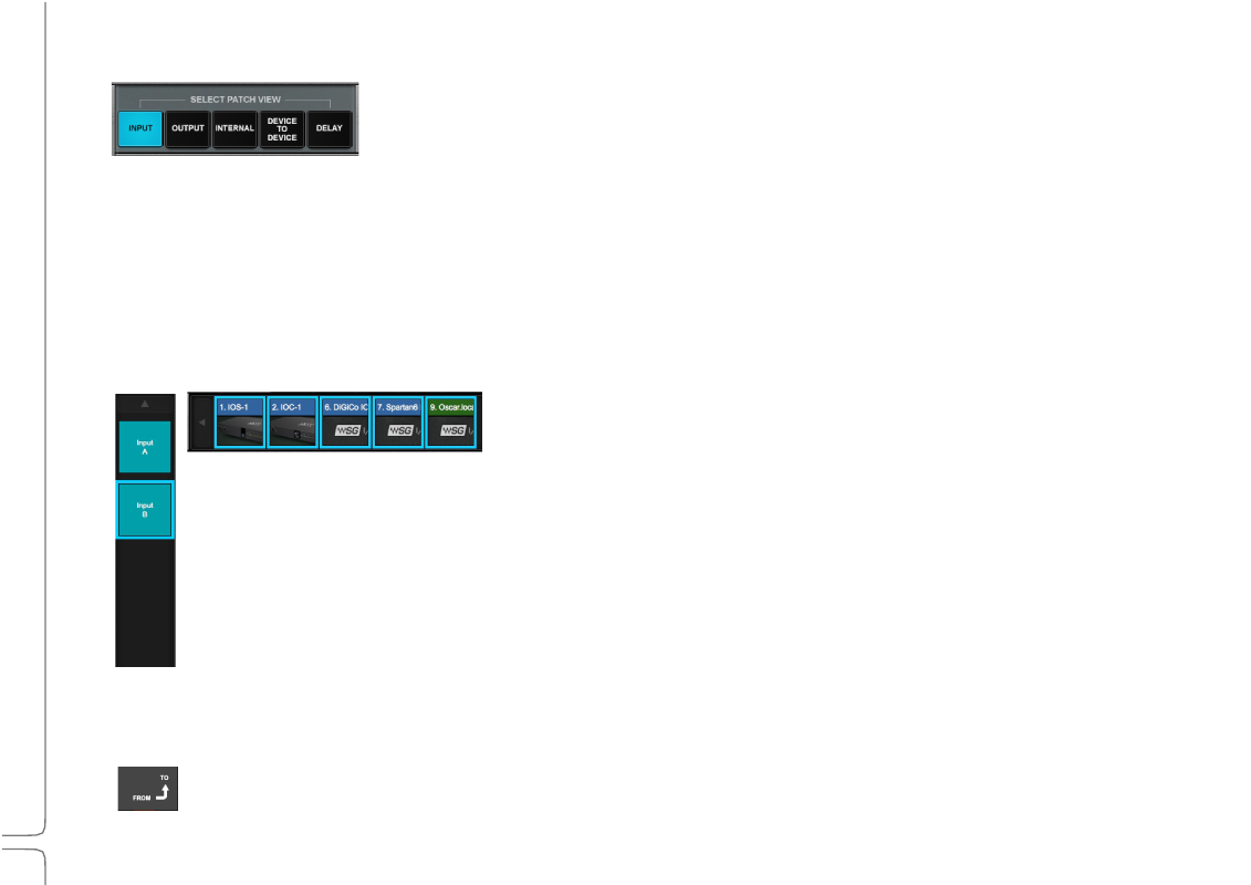
The grid filters on the left define the channels that make up the rows of the grid. These are usually mixer channels, except in the
Device-to-Device and Delay views.
Columns of channels are defined by the top filters. These are almost always used to select I/O devices. The only exception is
the Internal view, where instead mixer busses are shown.
All I/O devices that have been assigned in the System Inventory page—both hardware and software I/Os—are displayed on the
filter frame (either left or top or both, depending on the purpose of the patch).
Navigating the Grid Filters
The scrolling arrows on each grid filter bar make for easier navigation within a long list of channels or devices.
Patch Direction
An arrow indicates whether patch signal flows from top to left or from left to top.