Channel input – Waves eMotion LV1 64-Channel Mixer with Axis One Custom Computer User Manual
Page 146
141
Waves eMotion LV1 User Guide |
Chapte
r
4:
Mixer
Window
Window
Channel
Input
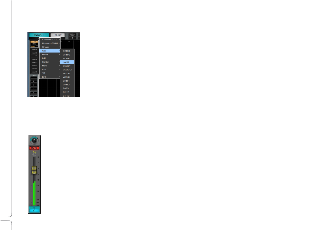
Channels 1–64 are input channels that patch to I/O devices, including shared devices. The number of
inputs available for patching is determined by the various devices assigned to the mixer.
•
Drop-down menus at the top of each channel strip show available I/O device channels.
•
An I/O channel can patch to several mixer input channels. Unavailable I/O channels are grayed out.
•
Once an I/O channel is selected, its name appears in the channel input name box just below
the channel name.
•
To change the input mode of the channel, select “Flip to Mono” or “Flip to Stereo.” When
converting a stereo track to mono, the top (left) channel will become the mono input. When
flipping from mono to stereo, only the left channel is patched.
M
ODE
C
ONTROLS
S
ECTION
This section is reserved for the Layer Mode controls. Each Layer Mode has its own graphic interface. Please refer to the section
Layer
Modes
later in this chapter.
C
HANNEL
P
ARAMETERS
S
ECTION
The bottom section of a channel strip is the same for all input and buss channels.
P
AN
/B
ALANCE
/R
OTATION
K
NOB
Pans mono channels between left and right when sent to a stereo buss. Controls the balance of a stereo signal or moves the
image wi
thout changing its internal balance. This multifunction controller is discussed in the next section.
C
HANNEL
M
UTE
A user-selected Mute for a specific channel will be solid red. A Mute activated by mute group, a DCA fader, or solo will flash
red.
When a mute button on a channel is flashing, click it again unmute it.
•
Click one more time to keep the channel muted even if the mute group is deactivated.
•
Click a third time to return to mute group behavior.
In the Solo-in-Place mode, the mute indicators on all channels (
except
the soloed channel) will flash red until solo is
cancelled.