ProSoft Technology PTQ-PDPMV1 User Manual
Page 38
Configuring the Module
PTQ-PDPMV1 ♦ Quantum Platform
User Manual
PROFIBUS DP Master Network Interface Module for Quantum
Page 38 of 306
ProSoft Technology, Inc.
August 12, 2014
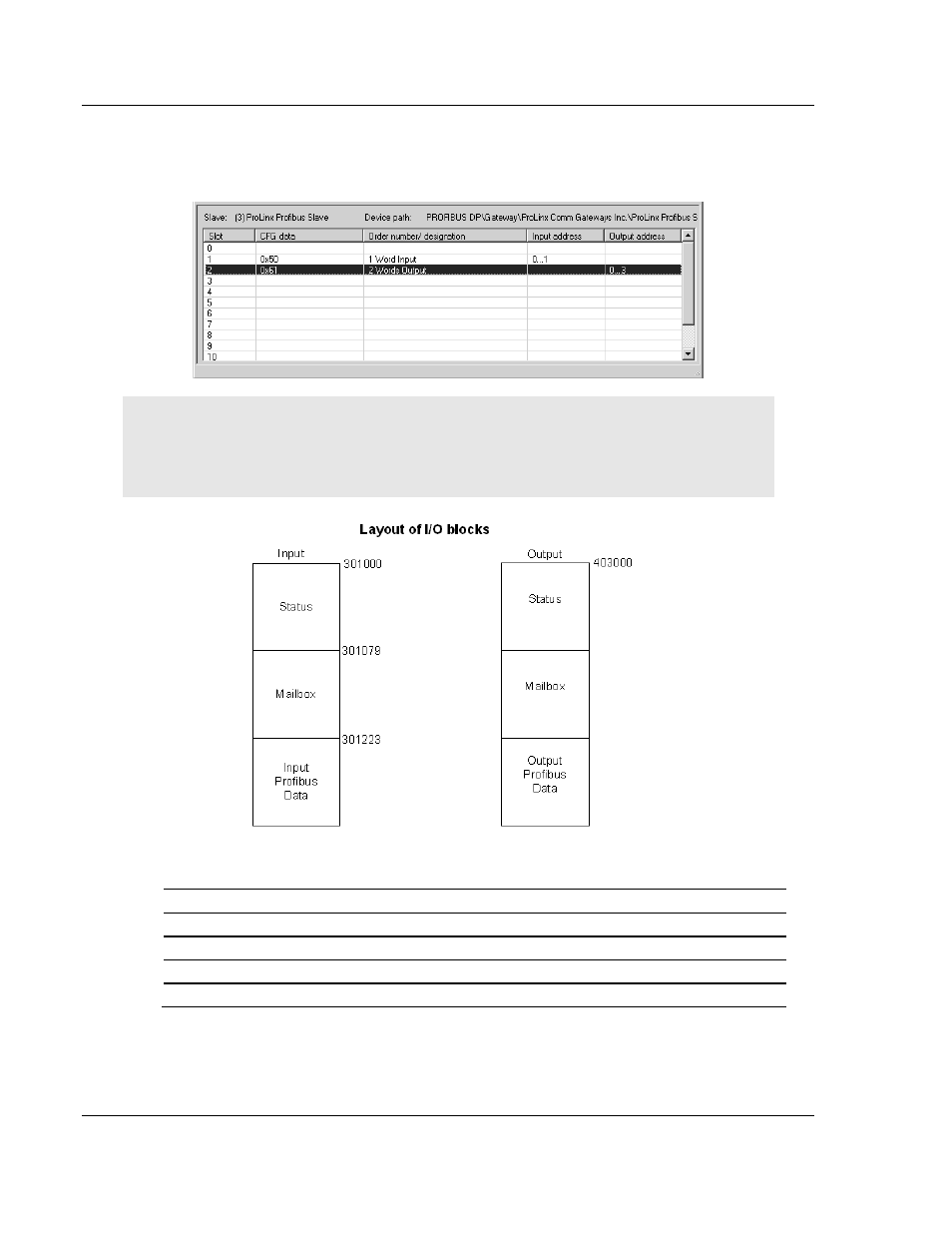
5 Drag the input and output parameters to the slot location grid below the Bus
Configuration window. This view displays the configuration data, order
number, and starting input and output addresses.
Important: The starting input and output addresses that you select here are actually byte offsets
within the PROFIBUS Data area inside each Input and Output backplane block.
For example, for the sample configuration for the input block, where the Input Start Register
Parameter = 1000:
The following table shows the actual Quantum address:
Input Address configured in PCB (Bytes) Actual Quantum Input Register Address (Words)
0...1
301223
2...3
301224
4...5
301225
...
...
- ILX69-PBS (102 pages)
- MVI69E-LDM (130 pages)
- ILX69-PBM (124 pages)
- MVI69L-MBTCP (152 pages)
- PS69-DPS (108 pages)
- MVI69E-MBTCP (150 pages)
- MVI69L-MBS (154 pages)
- MVI69E-MBS (162 pages)
- PS69-DPM (130 pages)
- MVI69-FLN (137 pages)
- MVI69-DFNT (167 pages)
- MVI69-GEC (86 pages)
- MVI69-PDPS (96 pages)
- MVI46-S3964R (80 pages)
- MVI46-S3964R (78 pages)
- MVI46-DNPSNET (119 pages)
- MVI69-ADMNET (122 pages)
- MVI56-104S (188 pages)
- MVI69-ADM (342 pages)
- MVI69-MCM (167 pages)
- 5307-MBP-HART (169 pages)
- MVI69-PDPMV1 (225 pages)
- MVI69-GSC (102 pages)
- MVI69-DNP (129 pages)
- MVI69-DFCM (117 pages)
- MVI69-103M (131 pages)
- PC56-OPC (34 pages)
- MVI46-MBP (101 pages)
- MVI69-101S (149 pages)
- MVI56-103M (152 pages)
- MVI56-DFCMR (113 pages)
- MVI56-DNP (193 pages)
- MVI56-LTQ (98 pages)
- ILX56-MM (112 pages)
- MVI56-BAS (234 pages)
- MVI56-DFCM (106 pages)
- MVI46-PDPS (88 pages)
- MVI56E-MNETCR (159 pages)
- MVI46-AFC (316 pages)
- MVI56E-MNETC (183 pages)
- MVI56E-GSC/ GSCXT (140 pages)
- MVI56-PDPMV1 (255 pages)
- MVI46-MNETC (153 pages)
- CLX-APACS (53 pages)
- MVI56E-MNET/MNETXT (181 pages)