ProSoft Technology PTQ-PDPMV1 User Manual
Page 114
Configuring the Processor with Concept 2.6
PTQ-PDPMV1 ♦ Quantum Platform
User Manual
PROFIBUS DP Master Network Interface Module for Quantum
Page 114 of 306
ProSoft Technology, Inc.
August 12, 2014
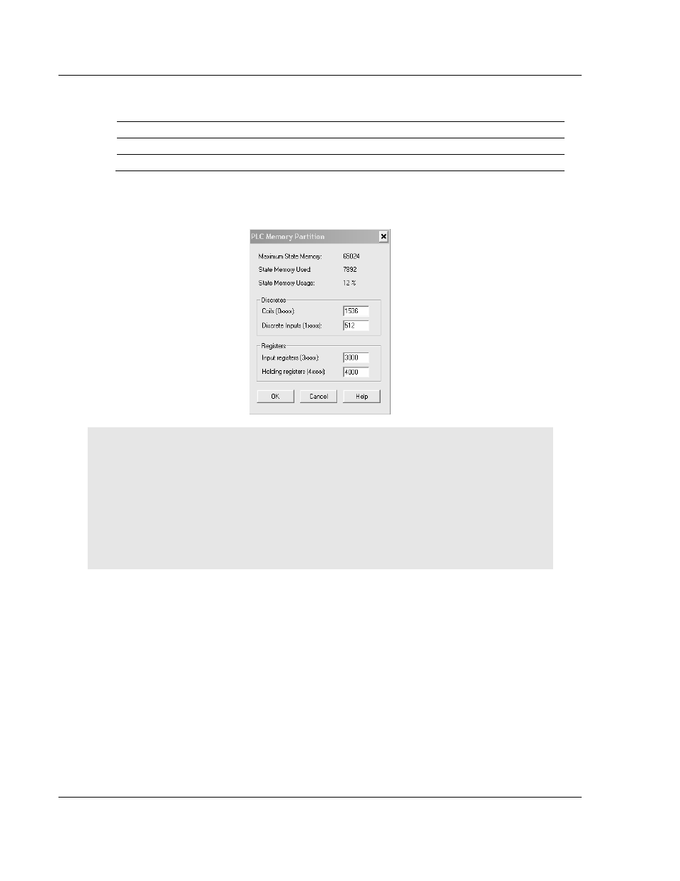
Using the example in the illustration, note the following values:
Total Size
Start Address
Last Address
PROFIBUS Input
991
301000
301990
PROFIBUS Output
918
403000
403917
For this example, select 3000 input registers and 4000 holding registers as
shown in the following illustration.
Note: Use these values for reference only. The illustration above indicates that you can only use
2000 registers, because the start register is at 1000 and the count is 3000. If your input requires
more than 2000 registers, refer to the following paragraph.
Important: You must configure the number of registers required for your application correctly,
otherwise the backplane driver will not transfer any data between the processor and the module.
Please note that the Input Data Size and Output Data Size parameters configured in PCB will
configure only the number of registers required for PROFIBUS data. However, the module will
require more registers for status and mailbox transfer. For this reason, you must verify the total
number of registers through the Diagnostics window.
7 In Concept, open the
F
ILE
menu, and then choose
C
LOSE
P
ROJECT
.