Quantum to ptq communication protocol – ProSoft Technology PTQ-PDPMV1 User Manual
Page 286
Reference
PTQ-PDPMV1 ♦ Quantum Platform
User Manual
PROFIBUS DP Master Network Interface Module for Quantum
Page 286 of 306
ProSoft Technology, Inc.
August 12, 2014
9.7
Quantum to PTQ Communication Protocol
The vehicle utilized for transferring data between the PTQ module and the
processor are two blocks of data:
PTQ Input Data block
PTQ Output Data block
Each of these data blocks (controlled by the PTQ) consists of a structure of data
that provides for the movement of:
Input Data image from PROFIBUS slave devices
Output Data image for writing to PROFIBUS slave devices
PTQ Module Configuration and Status (from PTQ to processor)
PROFIBUS Messaging Mailbox commands (from processor to PTQ)
PROFIBUS Messaging Mailbox responses (from PTQ to processor)
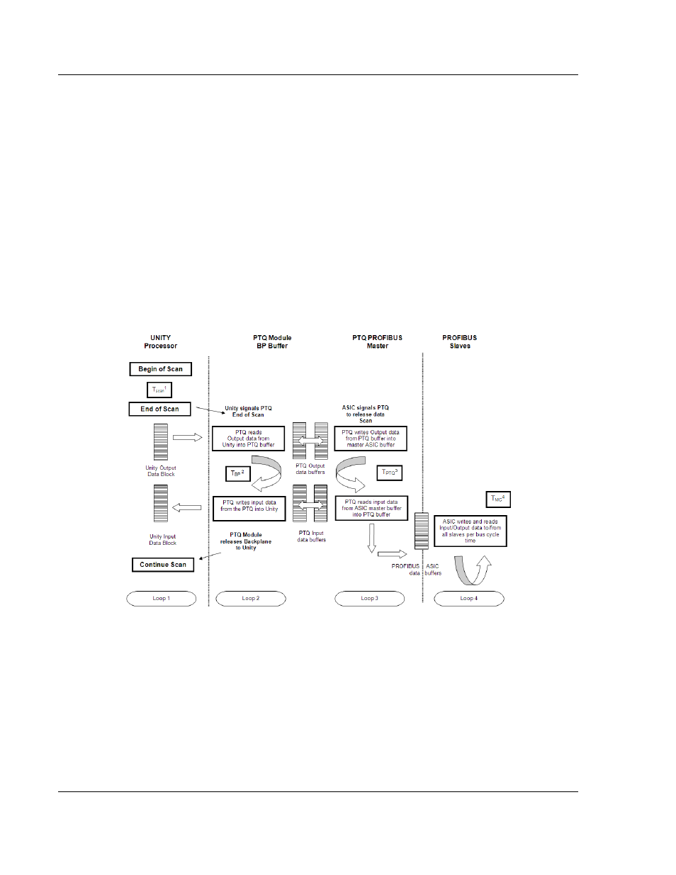
It is important to understand the process and flow of this data. The following
illustration describes the mechanism in a block diagram overview. Several
asynchronous data transfer loops occur simultaneously.
PLC Scan Loop 1
The PLC processor performs cyclic program, backplane, and network
communication tasks for each PLC scan time. This time is referred to in this
document as T
SCAN
time. Refer to the Quantum processor manual for additional
PLC cyclic task processing information.