Yaskawa VS-626 MC5 User Manual
Page 89
Setting User Constants
4.2.6 Programming Mode
- 26
4.2.6 Programming Mode
The Inverter user constants can be set in programming mode. The user constants which can be changed
and displayed depend on the access level and control method that are being used. Refer to the following
table to determine if a user constant can be changed.
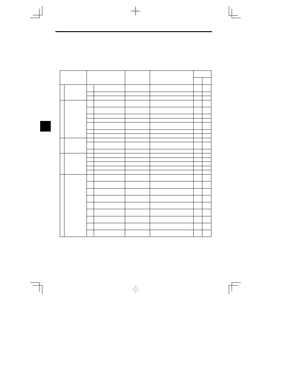
The groups of constants in programming mode and their functions are shown in Table 4.5.
Table
4.5
Programming Mode Constant Groups
Group
Function
Display
Comments
Control
Method
Group
Function
Display
Comments
Over
Loop
Vector
Flux
Vector
b
A
li
ti
b1
Operating modes
Sequence
Settings such as the reference input
method
b
Application
b2
DC braking
DC Braking
DC braking function settings
b3
Speed searching
Speed Search
Speed search function settings
C1
Acceleration/deceleration
times
Accel/Decel
Acceleration/deceleration time settings
C2
S-curve acceleration/de-
celeration
S-Curve Acc/Dec
S-curve characteristics for accel/decel
times
C T
i
C3
Slip compensation
Motor-Slip Comp
Slip compensation function settings
C Tuning
C4
Torque compensation
Torque Comp
Torque compensation function settings
C5
Speed control
ASR Tuning
Speed control loop user constant set-
tings
C6
Carrier frequencies
Carrier Freq
Carrier frequency settings
C8
Factory tuning constants
Factory Tuning
Adjustment for open-loop vector control
d1
Frequency references
Preset Reference
Operator frequency reference settings
d
Reference
d2
Frequency upper/lower
limits
Reference Limits
Frequency upper and lower limit set-
tings
d3
Jump frequencies
Jump Frequencies
Prohibited frequency settings
E1
V/f characteristics
V/f Pattern
Sets the motor V/f characteristics.
E2
Motor constants
Motor Setup
Sets the motor constants.
E
Motor
E3
Motor 2 control method
Motor 2 Ctl Meth
Sets the control methods for motor 2.
E4
V/f Characteristics 2
V/F pattern 2
Sets the V/f characteristics for motor 2.
E5
Motor 2 constants
Motor 2 Setup
Sets the motor constants for motor 2.
F1
PG speed control card
settings
PG Option Setup
User constant settings for a PG Card
F2
Analog Reference Card
AI
AI-14 Setup
User constant settings for an Analog
Reference Card
F3
Digital Reference Card DI
DI-08, 16 Setup
User constant settings for a Digital Ref-
erence Card
F4
Analog Monitor Card AO
AO-08, 12 Setup
User constant settings for an Analog
Monitor Card
F
Options
F5
Digital Output Card DO
DO-02C
User constant settings for a Digital Out-
put Card
F6
Digital Output Card DO
DO-08
User constant settings for a Digital Out-
put Card
F7
Pulse Monitor Card PO
PO-36F Setup
User constant settings for a Pulse Moni-
tor Card
F8
SI-F/SI-G Transmission
Card
SI-F/G
User constant settings for a Transmis-
sion Card
F9
CP-916B Transmission
Card
DDS/SI-B
User constant settings for a Transmis-
sion Card
4