Yaskawa VS-626 MC5 User Manual
Page 143
7.1
Open-loop Vector Control
- 5
7.1.2 Adjusting Speed Feedback
With open-loop vector control, internal Inverter data is used to calculate the feedback value. The gain of
this automatic frequency regulator (AFR) operation can be fine-tuned according to motor response. (Nor-
mally it isn’t necessary to change the default setting.)
J
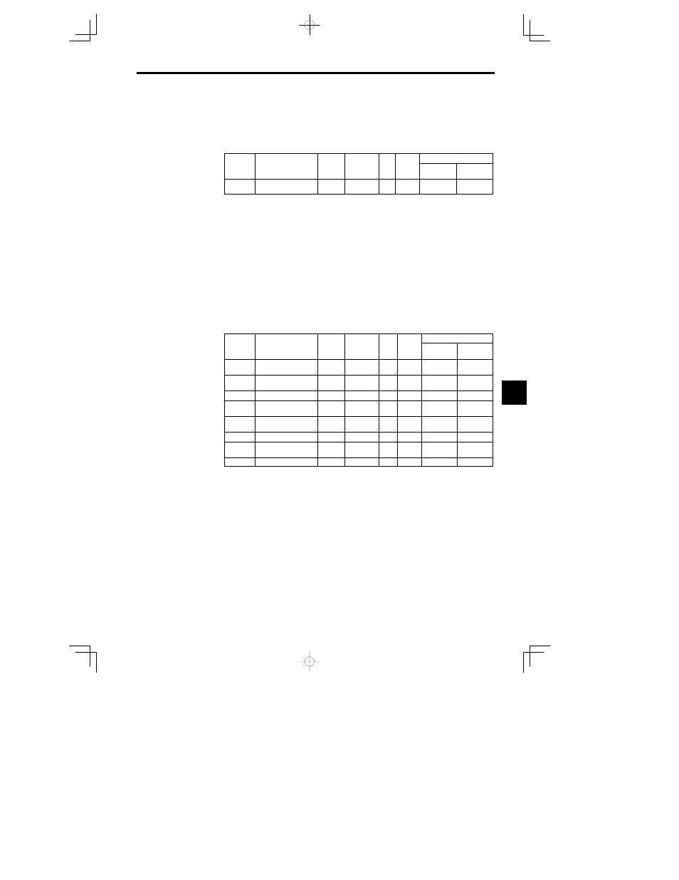
Speed Feedback Detection Control (AFR) Gain: C8-08
User
Change
during
Setting
Factory
Valid Access Levels
User
Constant
Number
Name
during
Opera-
tion
Setting
Range
Unit
Factory
Setting
Open Loop
Vector
Flux Vector
C8-08
AFR gain
0.00 to
10.00
Mul-
tiple
1.00
A
D
Normally it isn’t necessary to change this setting.
D
Fine-tune the gain when motor operation is unstable causing hunting to occur or torque/speed respon-
siveness is low.
x
When hunting occurs, increase the gain by 0.05 increments while checking the motor responsive-
ness.
x
When responsiveness is low, decrease the gain by 0.05 increments while checking the motor re-
sponsiveness.
7.1.3 Setting/Adjusting Motor Constants
J
Adjusting the V/f Pattern: E1-04 through E1-10, E1-13
Normally it isn’t necessary to adjust the V/f pattern with open-loop vector control. Adjust the V/f pattern
when you want to change the maximum output frequency setting or decrease the Inverter’s output voltage
or when stalls are occurring during no-load operation.
To increase the motor’s rated speed, increase the maximum output frequency in E1-04 in programming
mode after autotuning.
It is possible to make user-defined V/f pattern settings (E1-04 through E1-10) in open-loop vector control
mode. (The preset V/f patterns cannot be selected.)
User
Change
during
Setting
Factory
Valid Access Levels
User
Constant
Number
Name
during
Opera-
tion
Setting
Range
Unit
Factory
Setting
Open Loop
Vector
Flux Vector
E1-04
Max. output
frequency
40.0 to
400.0
Hz
60.0
Q
Q
E1-05
Max. voltage
0.0 to 255.0
*1
VAC
200.0
*1
Q
Q
E1-06
Base frequency
0.0 to 400.0
Hz
60.0
Q
Q
E1-07
Mid. output
frequency
0.0 to 400.0
Hz
3.0
*2
A
E1-08
Mid. output
frequency voltage
0.0 to 255.0
*1
VAC
11.0
*1 *2
A
E1-09
Min. output frequency
0.0 to 400.0
Hz
0.5
Q
A
E1-10
Min. output
frequency voltage
0.0 to 255.0
*1
VAC
2.0
*1 *2
A
E1-13
Base voltage
0.0 to 255.0
VAC
0.0
Q
Q
* 1. These voltages are for 200 V class Inverters; double the voltage for 400 V class Inverters.
* 2. The default setting depends on the Inverter’s capacity. The default settings shown in the table
are for 200 V class, 0.4 to 1.5 kW Inverters. (See page NO TAG.)
Note 1.The default settings for E1-07 through E1-10 depend on the control method. The default
settings shown in the table are for open-loop vector control. (See page NO TAG.)
2. The four frequency settings must satisfy the following formula:
E1-04 (F
MAX
)
t E1-06 (F
A
) > E1-07 (F
B
)
t E1-09 (F
MIN
)
3. When making the V/f characteristics a straight line, set the same value in E1-07 (middle
output frequency) and E1-09 (minimum output frequency). In this case, constant E1-08
(middle output frequency voltage) will be disregarded.
4. If E1-13 is set to 0.0, the same value as in E1-13 will be set for E1-05. It does not normally
need to be set separately.
7