Yaskawa VS-626 MC5 User Manual
Page 230
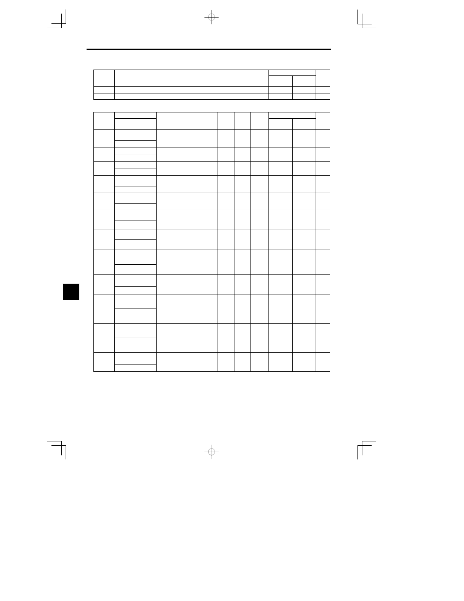
User Constants
8.2.6 Terminal Constants: H
- 22
Setting
value
Page
Control Methods
Function
Setting
value
Page
Flux vector
Open loop
Vector
Function
40
Zero speed 2 (ON: Zero speed, not included during Y/ winding change)
41
Motor selection (ON:During moter 2 selection)
- 41
J
Analog Inputs: H3
Constant
Name
Setting
Factory
Change
during
Control Methods
Constant
Number
Display
Description
Setting
Range
Factory
Setting
g
during
Opera-
tion
Open Loop
Vector
Flux Vector
Page
H3-01
Signal level selection
(terminal 13)
0: 0 to 10V [11--bit + polarity
(positive/negative) input]
0 1
0
B
B
- 4
H3 01
Term 13 Signal
(pos t ve/ egat ve)
put]
1: 0 to 10V
0 1
0
B
B
- 4
H3-02
Gain (terminal 13)
Sets the frequency when 10 V is in-
put as a percentage of the maxi
0.0 to
100 0
B
B
6
H3-02
Terminal 13 Gain
put, as a percentage of the maxi-
mum output frequency.
0.0 to
1000.0
100.0
B
B
- 6
H3-03
Bias (terminal 13)
Sets the frequency when 0 V is in-
put as a percentage of the maxi
--100.0
to
0 0
B
B
6
H3-03
Terminal 13 Bias
put, as a percentage of the maxi-
mum frequency.
to
+100.0
0.0
B
B
- 6
H3-04
Signal level selection
(terminal 16)
0: 0 to 10V [11--bit + polarity
(positive/negative) input]
0 1
0
B
B
- 6
H3 04
Term 16 Signal
(pos t ve/ egat ve)
put]
1: 0 to 10V
0 1
0
B
B
- 6
H3-05
Multi-function analog
input (terminal 16)
Select from the functions listed in
the following table. Refer to page
0 to 1F
0
B
B
- 44
H3 05
Terminal 16 Sel
the following table. Refer to page
- 44.
0 to 1F
0
B
B
- 44
H3-06
Gain (terminal 16)
Sets the input gain (level) when ter-
minal 16 is 10 V.
0.0 to
100 0
B
B
6
H3-06
Terminal 16 Gain
a
6 s 0 V.
Set according to the 100% value on
page - 44.
0.0 to
1000.0
100.0
B
B
- 6
H3-07
Bias (terminal 16)
Sets the input gain (level) when ter-
minal 16 is 0 V.
--100.0
to
0 0
B
B
6
H3-07
Terminal 16 Bias
a
6 s 0 V.
Set according to the 100% value on
page - 44
to
+100.0
0.0
B
B
- 6
H3-08
Signal level selection
(terminal 14)
0: 0 to +10 V (Always cut jumper
wire J1)
1: 0 to
r10 V (Always cut jumper
0 to 2
2
A
A
6 - 4
H3 08
Term 14 Sel
1: 0 to
r10 V (Always cut jumper
wire J1)
2: 4 to 20 mA (10--bit input)
0 to 2
2
A
A
6 - 4
H3-09
Multi-function analog
input (terminal 14)
Set as for H3-05.
Cannot be set to 0. The 1F func-
tion
ill b com “fr q
nc r f
1 to 1F
1F
A
A
- 4
44
H3 09
Terminal 14 Sel
tion will become “frequency ref-
erence.”
1 to 1F
1F
A
A
- 44
H3-10
Gain (terminal 14)
Sets the input gain (level) when ter-
minal 14 is 10 V (20 mA).
Set according to the 100% value on
0.0 to
100 0
A
A
6
H3-10
Terminal 14 Gain
Set according to the 100% value on
page - 44.
If H3-09 = 1F the setting in
H3-02 is used.
0.0 to
1000.0
100.0
A
A
- 6
H3-11
Bias (terminal 14)
Sets the input gain (level) when ter-
minal 14 is 0 V (4 mA).
Set according to the 100% value on
--100.0
to
0 0
A
A
6
H3-11
Terminal 14 Bias
Set according to the 100% value on
page - 44.
If H3-09 = 1F the setting in
H3-03 is used.
to
+100.0
0.0
A
A
- 6
H3-12
Analog input filter
time constant
Sets terminals 13, 14, 16 to primary
delay filter time constant, in sec-
onds units
0.00 to
2 00
0.00
A
A
- 7
H3 12
Filter Avg Time
onds units.
Effective for noise control etc.
2.00
0.00
A
A
- 7
8