Yaskawa VS-626 MC5 User Manual
Page 110
6.1
Common Settings
- 7
D
Responsiveness decreases as the setting increases.
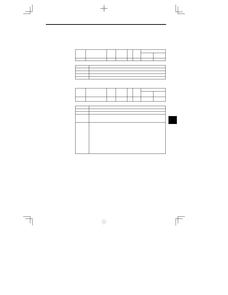
6.1.3 Frequency Reference from Digital Operator: b1-01, o1-03, d1-01 to d1-09
J
Frequency Reference Source: b1-01
D
Select the reference source.
User
Change
during
Setting
Factory
Valid Access Levels
User
Constant
Number
Name
during
Opera-
tion
Setting
Range
Unit
Factory
Setting
Open Loop
Vector
Flux Vector
b1-01
Reference selection
0 to 3
--
1
Q
Q
D
Settings
Setting
Reference source
0
Digital Operator
1
Control circuit terminals (analog inputs)
2
Transmission
3
Optional Card
D
The frequency reference is input from the Digital Operator, so set b1-01 to 0.
J
Frequency Unit for Reference Setting and Monitoring: o1-03
User
Change
during
Setting
Factory
Valid Access Levels
User
Constant
Number
Name
during
Opera-
tion
Setting
Range
Unit
Factory
Setting
Open Loop
Vector
Flux Vector
o1-03
Frequency unit for refer-
ence setting and monitor
0 to 39999
--
0
B
B
D
Settings
Setting
Function
0
0.01 Hz units
1
0.01% units (The maximum frequency is 100%.)
2 to 39
r/min units (Set the number of poles.)
r/min = 120
frequency reference (Hz)/o1--03
(o1--03 sets the motor poles.)
40 to 39999
Decimal point is set according to the 5th digit value of o1--03.
5th digit = 0: Displays
5th digit = 1: Displays
.
5th digit = 2: Displays
.
5th digit = 3: Displays .
Setting values of 100% frequency are set according to the first to fourth digits of o1--03
[Example 1]
When the setting value (100% speed) is 200.0, o1--03 is set to 12000.
When o1--03 is set to 12000, 100% speed displays 200.0. 60% speed displays 120.0.
[Example 2]
When the setting value (100% speed) is 65.00, o1--03 is set to 26500.
When o1--03 is set to 26500, 60% speed displays 39.00.
D
When the 40 to 39,999 range is used, any unit can be set for the reference frequency.
For example, the frequency reference can be displayed or set in units such as mm/s or m/min to coin-
cide with the linear operating speed of the machine.
6