Yaskawa VS-626 MC5 User Manual
Page 102
Trial Operation
5.2.6 No-load Operation
- 8
Display Message
Countermeasure
Description
Fault
PG Direction
Motor direction fault
There is a contact fault between
the Inverter, PG (phase A and B),
and motor (phases U, V, and W)
S Check the PG wiring.
S Check the motor wiring.
S Check the PG direction and constant F1-05.
Motor speed
Motor speed fault
The torque reference was too large
(100%) during autotuning.
S Disconnect the motor from the machine if
it has been connected.
S Increase the acceleration time (C1-01).
S Check the input data (particularly the num-
ber of PG pulses).
ALARM: Over Load
(Displayed after completion of
autotuning)
Tuning overload fault
The torque reference was over
20% during autotuning.
Check the input data (particularly the num-
ber of PG pulses) if the motor is being auto-
tuned separately.
Tune Aborted
Minor Fault:
Minor fault
A minor Inverter fault occurred.
Check the minor fault indicated in the boxes
in the display shown at the left.
Tune Aborted
V/f Over Setting
(Displayed after completion of
autotuning)
V/f Over Setting
Torque reference exceeded 100%,
and no--load current exceeded
70%.
S Check the setting.
S Disconnect the motor from the load.
D
Fault displays can be cleared by pressing the MENU Key.
D
All set constants (motor constants) will be initialized if a fault occurs. Reset the constants from the
beginning when before starting autotuning again.
5.2.6 No-load Operation
The section describes trial operation in which the motor is operated from the Digital Operator with the mo-
tor in the no-load state (with the motor not connected to the mechanical system).
J
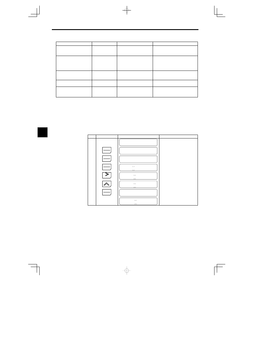
Setting the Frequency Reference
Set the frequency reference on the frequency reference monitor in the operation mode.
The following is an operation example with the frequency reference set to 10 Hz.
Step
Key Sequence
Digital Operator Display
Remarks
MC5
Main Menu
Operation
Displays operation mode.
1
DATA
ENTER
Frequency Ref
U1-01 = 0.00 HZ
Puts the Unit in operation mode and
displays the frequency reference.
2
LOCAL
REMOTE
Frequency Ref
U1-01 = 0.00 HZ
Switches operation to the Digital Op-
erator. (SEQ, REF and LED indica-
tors turn OFF.)
3
DATA
ENTER
Frequency Ref
000.00 HZ
Sets the frequency reference.
4
RESET
Frequency Ref
000. 00HZ
The tens digit blinks.
5
Frequency Ref
010. 00HZ
Set to 010.00 Hz.
6
DATA
ENTER
Entry Accepted
The set values are overwritten.
Frequency Ref
010. 00 HZ
Returns to the frequency reference
display.
5