Yaskawa VS-626 MC5 User Manual
Page 109
Basic Operation
6.1.2 Frequency Reference Settings: b1-01, H3-01, H3-08, H3-09
- 6
Signal Level for Multi-function Analog Input, Terminal 16: H3-04
D
Set the signal level for the multi-function analog input.
User
Change
during
Setting
Factory
Valid Access Levels
User
Constant
Number
Name
during
Opera-
tion
Setting
Range
Unit
Factory
Setting
Open Loop
Vector
Flux Vector
H3-04
Signal level selection
(terminal 16)
0 1
--
0
B
B
D
Settings
Setting
Function
0
0 to 10 VDC input [11--bit + polarity (positive/negative) input]
1
--10 to 10 VDC input
(A negative voltage is a reference for reverse rotation.)
J
Adjusting Analog Inputs: H3-02, H3-03, H3-06, H3-07, H3-10, H3-11, H3-12
D
There are three constants used to adjust the analog inputs: The gain, bias (both set separately for each
input), and filter time constant (a single value for all of the inputs).
x
The gain and bias can be adjusted separately for each analog input (terminals 13, 14, and 16).
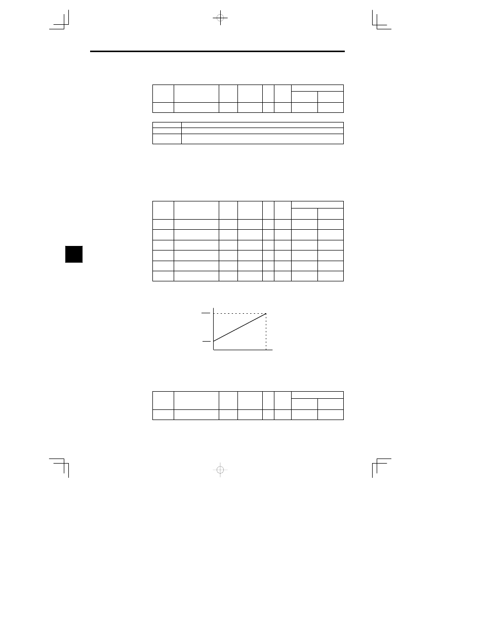
Gain:
Set the frequency corresponding to a 10 V (20 mA) input as a percentage of the
maximum frequency. (The maximum output frequency set in E1-04 is 100%.)
Bias:
Set the frequency corresponding to a 0 V (4 mA) input as a percentage of the
maximum frequency. (The maximum output frequency set in E1-04 is 100%.)
x
Set the gains and biases for terminals 13, 14, and 16 as follows:
User
Change
during
Setting
Factory
Valid Access Levels
User
Constant
Number
Name
during
Opera-
tion
Setting
Range
Unit
Factory
Setting
Open Loop
Vector
Flux Vector
H3-02
Gain for terminal 13
0.0 to
1000.0
%
100.0
B
B
H3-03
Bias for terminal 13
--100.0 to
100.0
%
0.0
B
B
H3-10
Gain for terminal 14
0.0 to
1000.0
%
100.0
A
A
H3-11
Bias for terminal 14
--100.0 to
100.0
%
0.0
A
A
H3-06
Gain for terminal 16*
0.0 to
1000.0
%
100.0
B
B
H3-07
Bias for terminal 16*
--100.0 to
100.0
%
0.0
B
B
*
The settings for terminal 16 are valid only when the multi-function analog input has been se-
lected. The gain and bias set here will be disregarded if a frequency reference is selected and
the values set for terminal 13 will be used.
Frequency
reference
0 V
(
4 mA
)
10 V
(
20 mA
)
Use the current values shown in
parentheses when current input
has been selected.
Max. output frequency
u
Gain
100
Max. output frequency
u
Bias
100
Fig
6.2
Gain and Bias Chart
Analog Input Filter Time Constant: H3-12
D
A primary delay digital filter can be set for all three analog inputs (frequency reference (voltage), fre-
quency reference (current), and multi-function analog input)
User
Change
during
Setting
Factory
Valid Access Levels
User
Constant
Number
Name
during
Opera-
tion
Setting
Range
Unit
Factory
Setting
Open Loop
Vector
Flux Vector
H3-12
Analog input filter time
constant
0.00 to 2.00
s
0.00
A
A
D
This setting is effective when there are sudden changes or noise in the analog input signal.
6